
Imaging apparatus and process of forming image with electrophotographic photoreceptor having protective layer containing particulate P-type semiconductor

a technology of electrophotographic photoreceptor and image, which is applied in the direction of electrographic process apparatus, optics, instruments, etc., can solve the problems of affecting the quality of images, so as to achieve stable cleaning characteristics and high quality. the effect of stability

Active Publication Date: 2018-01-16
KONICA MINOLTA INC
View PDF16 Cites 0 Cited by
  • Summary
  • Abstract
  • Description
  • Claims
  • Application Information

AI Technical Summary

Benefits of technology

The solution provides long-term stable cleaning characteristics and high-quality image formation by controlling lubricant application, preventing fogging and blurring, and maintaining the photoreceptor's surface integrity.

Problems solved by technology

Photoreceptors having fine scratches or irregularities generated due to wear of their surfaces degrade image quality.
Although such an imaging apparatus including a photoreceptor having a large surface roughness Rz disclosed in Patent Literature 1 increases the amount of the lubricant to be applied onto the photoreceptor, an excess lubricant accumulated on the surface of the photoreceptor readily causes fogging or blurring in images.
Control of the amount of the lubricant has technical difficulties in formation of a coating of the lubricant on the surface of the photoreceptor.

Method used


Image

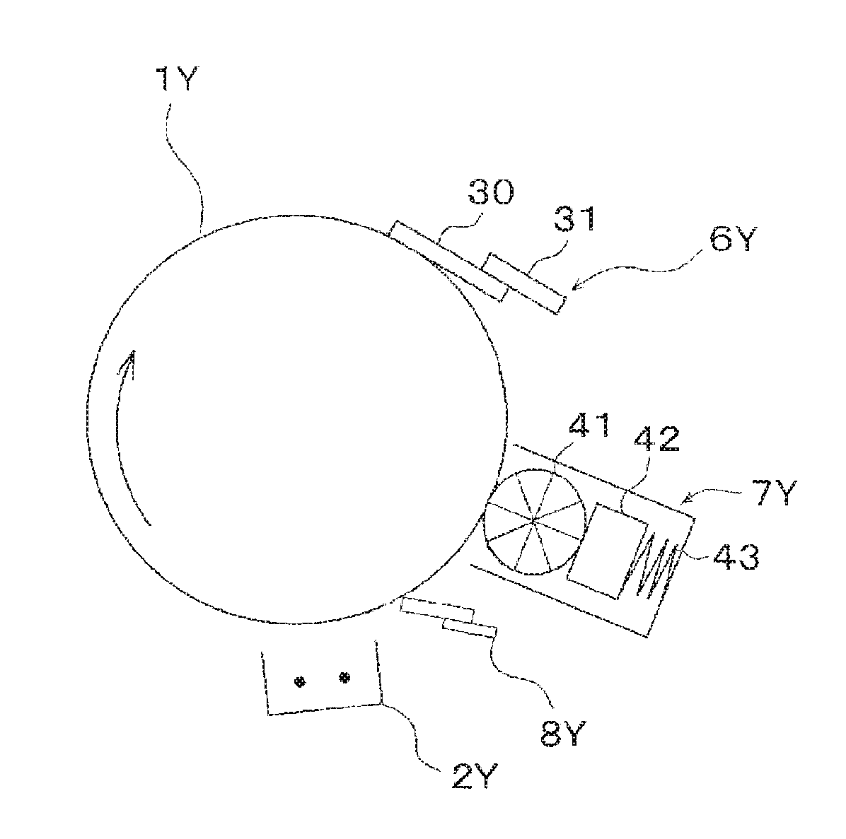
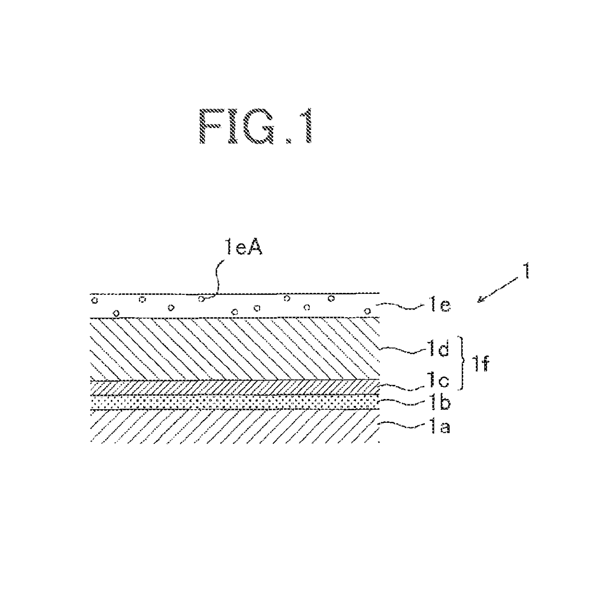
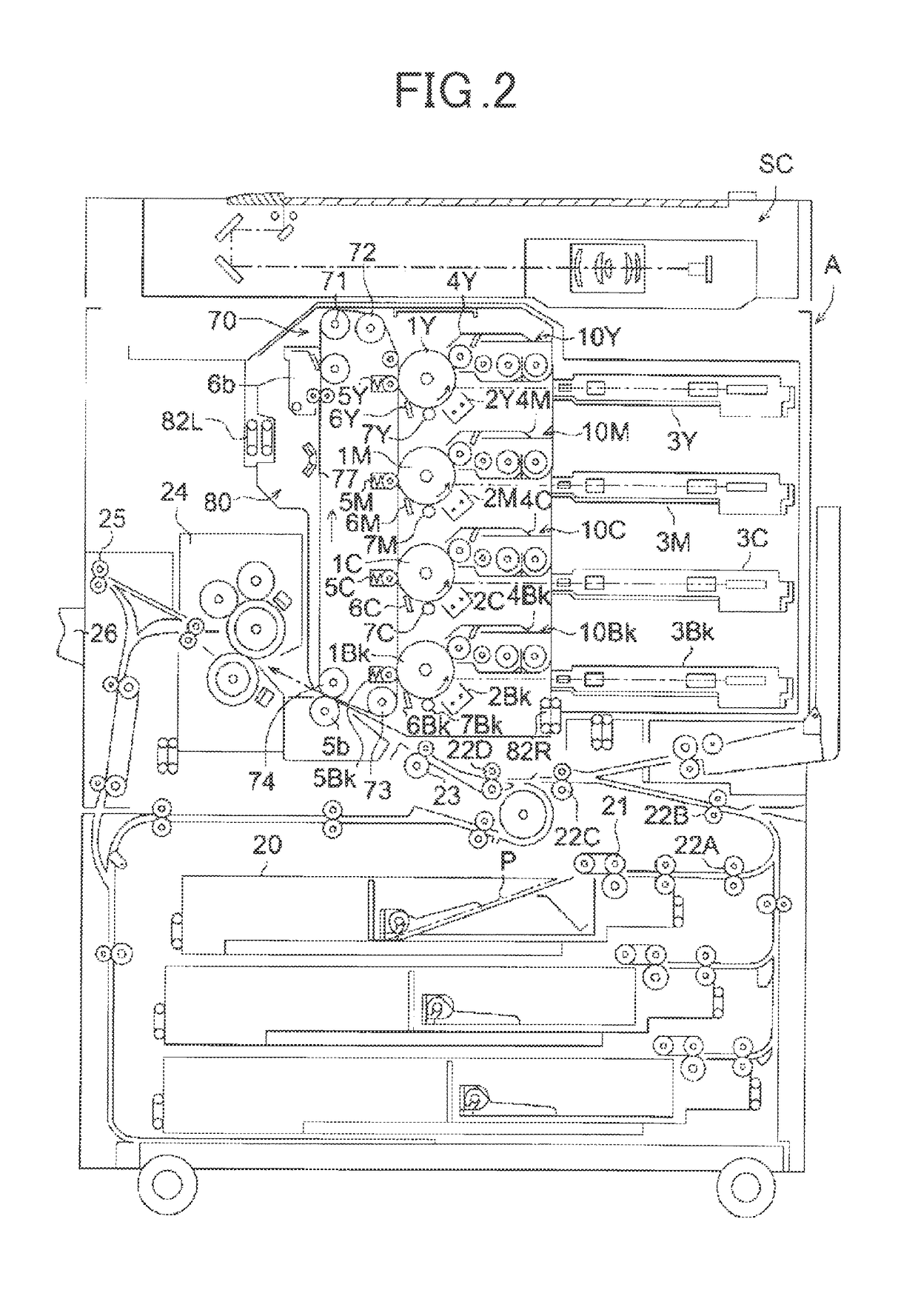
  • Imaging apparatus and process of forming image with electrophotographic photoreceptor having protective layer containing particulate P-type semiconductor
  • Imaging apparatus and process of forming image with electrophotographic photoreceptor having protective layer containing particulate P-type semiconductor
  • Imaging apparatus and process of forming image with electrophotographic photoreceptor having protective layer containing particulate P-type semiconductor

Examples


example 1

Preparative Example 1 of Photoreceptor

(1) Preparation of Conductive Support

[0176]A drum-shaped aluminum support (outer diameter: 60 mm) was prepared as Conductive support [1].

(2) Formation of Intermediate Layer

[0177]A polyamide binder resin (100 parts by mass) for an intermediate layer was added to a mixed solvent (1700 parts by mass) of ethanol, n-propyl alcohol, and tetrahydrofuran (volume ratio: 45 / 20 / 35), and was mixed through stirring at 20° C. To the solution, titanium oxide particles “SMT500SAS” (made by Tayca Corporation, 160 parts by mass) and titanium oxide particles “SMT150MK” (made by Tayca Corporation, 120 parts by mass) were added, and were dispersed with a bead mill at a mill residence time of five hours. The solution was left to stand all night and all day, and was separated through filtration to prepare a coating solution for forming an intermediate layer. The solution was filtered through a Rigimesh filter (made by Pall Corporation) having a nominal filtration rati...

example 2

Preparative Example 2 of Photoreceptor

[0187]Photoreceptor [2] was prepared as in Preparative Example 1 of photoreceptor except that the protective layer was formed as follows.

(5) Formation of Protective Layer

[0188]A coating solution composition composed of

[0189]

Polymerizable compound (Exemplified compound100 parts by mass(M1))Surface-treated particulate P-type semiconductor100 parts by mass(CuAlO2, number average primary particle size:50 nm)Polymerization initiator “IRGACURE 819” 5 parts by massmade by BASF SE)Solvent: 2-butanol330 parts by massSolvent: tetrahydrofuran 17 parts by mass

was sufficiently dissolved and dispersed with stirring to prepare Coating solution [2] for forming a protective layer. Coating solution [2] for forming a protective layer was applied onto Charge transporting layer [1] with a circular slide hopper applicator provided with a circular forced exhaust apparatus. The coating was irradiated with ultraviolet light from a xenon lamp for one minute, and was drie...

example 3

Preparative Example 3 of Photoreceptor

[0190]Photoreceptor [3] was prepared as in Preparative Example 1 of photoreceptor except that the protective layer was formed as follows.

(5) Formation of Protective Layer

[0191]A coating solution composition composed of

[0192]

Polymerizable compound (Exemplified compound100 parts by mass(M1))Surface-treated particulate P-type semiconductor100 parts by mass(CuAlO2, number average primary particle size:50 nm)Polymerization initiator: compound represented by 5 parts by massFormula (A)Solvent: 2-butanol330 parts by massSolvent: tetrahydrofuran 17 parts by mass

was sufficiently dissolved and dispersed with stirring to prepare Coating solution [3] for forming a protective layer.

[0193]Coating solution [3] for forming a protective layer was applied onto Charge transporting layer [1] with a circular slide hopper applicator, and the coating was dried at 120° C. for 70 minutes to form Protective layer [3] having a dry thickness of 3.0 μm and a surface roughnes...


PUM


Abstract

An imaging apparatus including: an electrophotographic photoreceptor; a charging unit to charge the surface of the electrophotographic photoreceptor; an exposing unit to perform exposure of the electrophotographic photoreceptor charged by the charging unit; a developing unit to feed a toner to the electrophotographic photoreceptor exposed by the exposing unit to form a toner image; a transfer unit to transfer the toner image formed on the electrophotographic photoreceptor; a lubricant feeding unit to feed a lubricant onto the surface of the electrophotographic photoreceptor; and a cleaning unit to remove the residual toner on the surface of the electrophotographic photoreceptor, wherein the electrophotographic photoreceptor includes a conductive support, a photoreceptive layer, and a protective layer disposed in sequence, the protective layer includes a resin containing a particulate P-type semiconductor, and the protective layer has a surface roughness Rz of 0.030 μm or more and 0.075 μm or less.

Description

BACKGROUND OF THE INVENTION[0001]1. Field of the Invention[0002]The present invention relates to imaging apparatuses and processes of forming images for forming electrophotographic images.[0003]2. Description of Related Art[0004]Electrophotographic photoreceptors included in electrophotographic imaging apparatuses (hereinafter, also simply referred to as “photoreceptors”) are responsible for formation of images having stable quality. Photoreceptors having fine scratches or irregularities generated due to wear of their surfaces degrade image quality.[0005]Accordingly, non-transferred toners remaining on the surface of the photoreceptor in such an electrophotographic imaging apparatus during an image forming process have been mechanically removed with a cleaning member. In addition, a lubricant has been applied onto the surface of the photoreceptor to form a coating of the lubricant on the surface of the photoreceptor. The coating of the lubricant reduces the frictional resistance bet...

Claims


Application Information

Patent Timeline
Patent Type & Authority Patents(United States)
IPC IPC(8): G03G5/00G03G5/147G03G15/00G03G21/00G03G5/082
CPCG03G5/147G03G5/082G03G5/08278G03G5/14791G03G15/751G03G21/0094G03G5/14704G03G2215/00957
Inventor FUJITA, TOSHIYUKIINAGAKI, KEIICHIISHIZUKA, KAZUTERUUEDA, MARIKODAMA, DAISUKE
Owner KONICA MINOLTA INC
Learn More