Production of fibre composite component part based on steel and polyurethane

a technology of fibre composite components and polyurethane, which is applied in the direction of natural mineral layered products, synthetic resin layered products, coatings, etc., can solve the problems of inability to process laminates of this type, the thickness of metal is immense, and the material science of manufacturing fibre composite component parts is accordingly much more difficult than the material science of producing component parts, etc., to achieve the effect of high component strength

Inactive Publication Date: 2018-02-27
EVONIK DEGUSSA GMBH
View PDF28 Cites 5 Cited by
  • Summary
  • Abstract
  • Description
  • Claims
  • Application Information

AI Technical Summary

Benefits of technology

[0059]The invention has an object to devise a method whereby fibre composite component parts are produced from steel and polyurethane in industrial practice and in a commercially viable manner. It is a fundamental concept of the method according to the present invention to use a polyurethane composition which is special in that it conforms to the manufacturing process, in that it is capable of undergoing a first crosslinking reaction to convert it into a thermoplastic polymer and later a second crosslinking reaction to fully crosslink the thermoplastic polymer into a thermoset material. According to the present invention, the full crosslinking into the thermoset polymer is only carried out after a shape-conferring forming step, and so the final high strength of the component part is only attained after the component part has already assumed its ultimate in-service shape. The invention is notable for closely harmonizing the choice of chemicals with the mechanical processing steps to thereby exploit synergies in the processing of plastics and of steel.

Problems solved by technology

The materials science of manufacturing fibre composite component parts is accordingly much more tricky than the materials science of producing component parts from homogeneous materials.
Producing such a component part is a supreme technical challenge, since the specific expertise of organic and inorganic chemistry, of metal processing and regarding the in-service conditions expected for the component part must be combined.
This method of production is disadvantageous in that it always leads to a planar laminate, the utility of which is limited by its flatness.
This method is incidentally also disadvantageous because of the rapid reaction of the isocyanate / polyol components to form the polyurethane, making it necessary to produce this composite component part under time pressure.
However, the thickness of the metal is an immense 2 to 20 mm, so the steel here is in the form of heavy plate which, unlike fine sheet (thickness <3 mm), is not coilable.
A laminate of this type is therefore impossible to process with a conventional panel press of the type used in automotive construction for example.
This method is disadvantageous in that the fibres, in the form of short fibre, are already present in the polyurethane raw material, thus preventing intentional alignment of the fibres in the direction of the later transmission / distribution of forces / stresses.
One disadvantage here is the aqueous formulation of the reactive polyurethane mixture, so water vapour has to escape from the laminate during the processing operation.
Unless all the water is successfully removed, internal corrosion of the steel sheets is likely.
In addition, the reported polyurethane composition is highly reactive, so shaping has to take place within a tight processing window.
Overall it appears to be questionable whether the method described in DE102012106206A1 is capable of producing a steel-PU composite component part on an industrial scale and in a commercially viable manner.
However, these storage-stable prepregs are disadvantageous in that they are not unreservedly useful for lamination with steel.
More particularly, they fail to achieve a sufficient level of steel-polymer bonding for safely forming a laminate obtained therefrom, as Example 0 will demonstrate herein below.
Consequently, no method has been described to date for obtaining fibre composite component parts from steel and a polyurethane on an industrial scale and in a commercially viable manner.

Method used


Image

  • Production of fibre composite component part based on steel and polyurethane
  • Production of fibre composite component part based on steel and polyurethane

Examples


examples

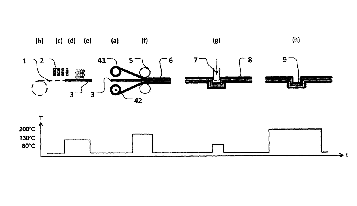
[0156]The following woven carbon fibre fabric was used as the textile fabric in all tests: Torayca FT 300 3K 200 tex 200 g / m2 twill weave.

[0157]All the tests were carried out using galvanized, cold rolled steel sheets 0.2 mm in sheet thickness. Standard steel sheets from ThyssenKrupp Steel Europe AG without dual-phase or bake-hardening structure were concerned.

[0158]The mixture used in Example 0, a comparative example not in accordance with the present invention, was a reactive polyurethane composition prepared as described in Example 2 of DE102011006163A1. The recipe is depicted in table 0.

[0159]The mixtures used for Inventive Examples 1 and 2 had recipes as per tables 1 and 2.

[0160]

TABLE 0Recipe of mixture for Comparative Example 0Comparative Example 0 (not in accordance with the present invention)Hardener (60%Uretdione65.3 wt %Evonikstrength)hardenerIndustries(Effective NCO: 7.7%Polyol 4640 (OHN 630Binder10.9 wt %Perstorpmg KOH / g molar mass360 g / mol liquidBenzoinDegassing agent 0...


PUM

PropertyMeasurementUnit
temperatureaaaaaaaaaa

Abstract

A method of producing a fiber composite component part, contains the following steps: a) providing two or more steel sheets; b) providing at least one textile fabric; c) providing an anhydrous mixture having one or more than one hardener containing a uretdione having an NCO functionality of not less than two, one or more than one binder having hydroxyl groups to an OH functionality of three to six, and one or more than one cobinder having oxirane groups; d) coating the textile fabric with the mixture; e) applying energy to the mixture-coated fabric for the purpose of performing a first crosslinking reaction to react hardener, binder and cobinder to form a thermoplastic polymer adhering to the textile fabric; f) hot pressing the steel sheets and the textile fabric together with the thermoplastic polymer adhering thereto into a sandwich such that the thermoplastic polymer joins the steel sheets together while enclosing the textile fabric; g) forming the sandwich into a shaped article; h) heat treating the shaped article to obtain the fiber composite component part, wherein the thermoplastic polymer undergoes a second crosslinking reaction to convert into a thermoset polymer.

Description

BACKGROUND OF THE INVENTION[0001]Field of the Invention[0002]The invention relates to the production of a fibre composite component part based on steel and polyurethane.[0003]Discussion of the Background[0004]Fibre composite component part refers to a component part which is a component part of a machine, of a land-, air-, space- or water-craft, of an apparatus, of an installation or of an appliance and which is constructed of different, indissolubly interconnected materials subject to the proviso that at least one material takes the form of fibres and at least one material takes the form of a matrix surrounding said fibres. The shape of this fibre composite component part is substantially the shape that is determined by its intended use. As a result, the fibre composite component part is virtually ready to install / use and, apart from minor secondary finishing, requires no further significant changes in shape before installation / use.[0005]The present fibre composite component part c...

Claims


Application Information

Patent Timeline
Patent Type & Authority Patents(United States)
IPC IPC(8): B29C43/02B32B19/02B32B27/04B32B27/40C08G18/79C09J5/06C08G18/58C08G18/40B32B15/18B32B15/14B32B15/08C08G18/42B32B37/20B29C70/34B32B38/12B32B38/00B32B37/10B29K63/00B29L9/00
CPCB29C43/021B32B15/08B32B15/14B32B15/18B32B19/02B32B27/04B32B27/40B32B37/203C08G18/4045C08G18/4269C08G18/58C08G18/798C09J5/06B29C70/34B32B2398/20B29K2063/00B29L2009/003B32B37/1027B32B38/12B32B2038/0076B32B2305/18B32B2309/02B32B2309/04B32B2309/12C08G18/3206C08G18/42C08G18/48C08J5/24C08K7/02C08K5/315C08J2375/04C08J2375/08B29B15/10B32B15/095B32B37/06B32B37/24B32B2037/243B32B2266/0278B32B2255/02B32B2255/10B32B2255/26
Inventor STAPPERFENNE, UWEREEMERS, SANDRAHALLACK, MARKUS
Owner EVONIK DEGUSSA GMBH
Why Eureka
Try Eureka