

Nitride semiconductor device
- Summary
- Abstract
- Description
- Claims
- Application Information
AI Technical Summary
Benefits of technology
Problems solved by technology
Method used
Image

Examples
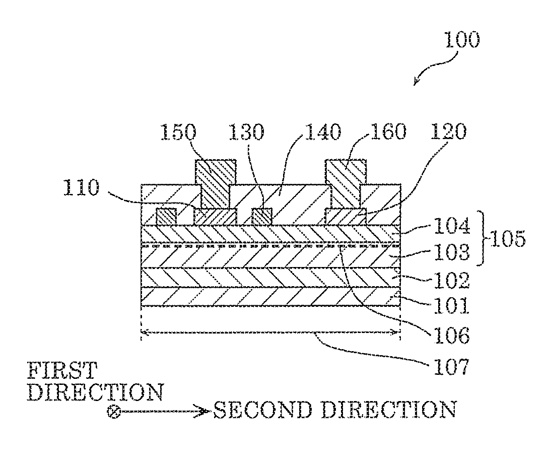
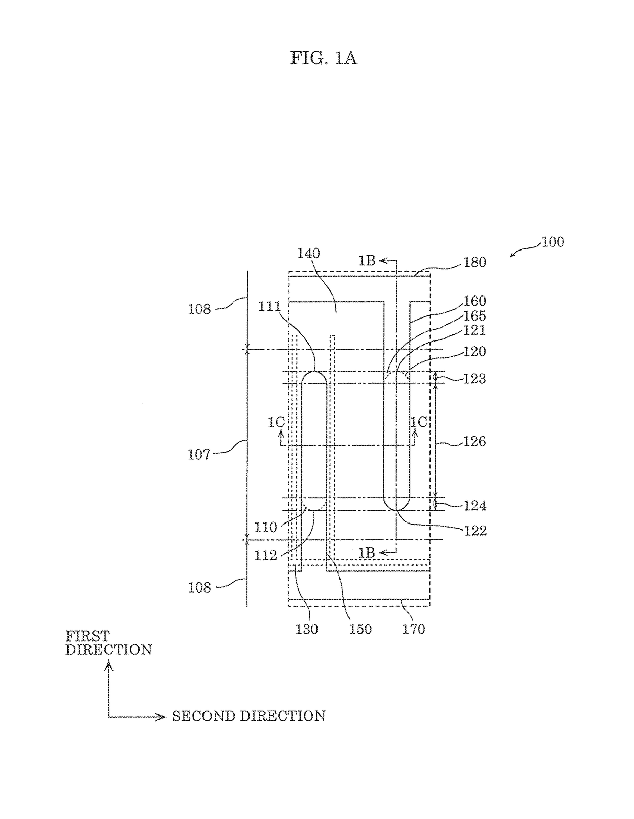
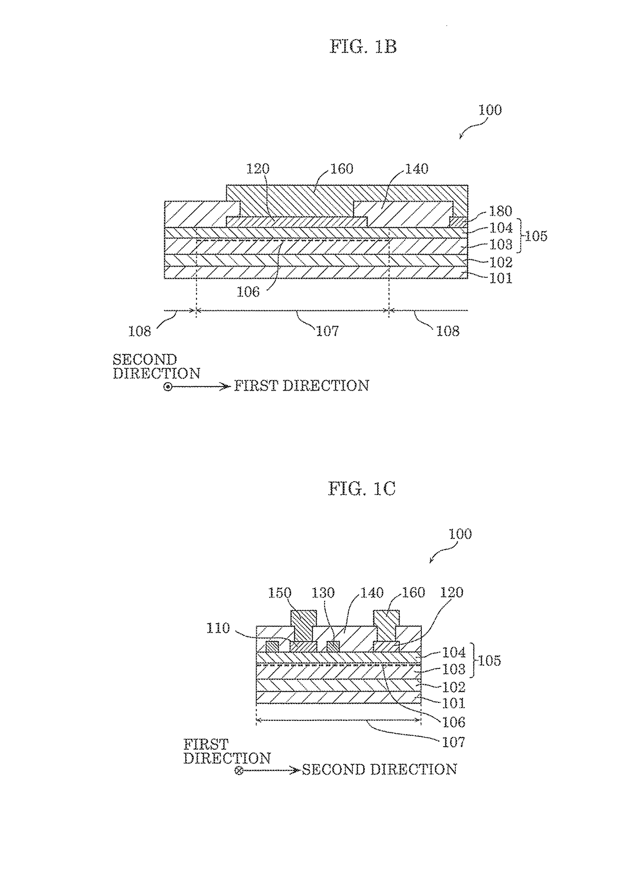
embodiment 1
Modification of Embodiment 1
[0101]Hereinafter, a nitride semiconductor device according to a modification of Embodiment 1 will be described with reference to the drawings.
[0102]FIG. 1H is a plan view of a layout of nitride semiconductor device 100d according to this modification. FIG. 1I is a cross-sectional view of nitride semiconductor device 100d according to this modification at cross section 1I-1I in FIG. 1H. FIG. 1J is a cross-sectional view of nitride semiconductor device 100d according to this modification at cross section 1J-1J in FIG. 1H.
[0103]Since the configuration of nitride semiconductor device 100d according to this modification other than insulating film 140d and second lead-out line 160 is the same as the configuration of nitride semiconductor device 100c described above using FIG. 1G, overlapping description will be omitted. Furthermore, in this modification, the thickness of insulating film 140d needs to be increased so that the position of second lead-out line 16...
embodiment 2
[0107]Hereinafter, a nitride semiconductor device according to Embodiment 2 will be described. The nitride semiconductor device according to this embodiment is different from nitride semiconductor device 100 according to Embodiment 1 in the point of including hole injection portions for reducing electrons trapped in the surface of stacked structure portion 105. Hereinafter, the nitride semiconductor device according to this embodiment will be described with reference to the drawings, centering on the points of difference with nitride semiconductor device 100 according to Embodiment 1.
[0108]FIG. 2A is a plan view of a layout of nitride semiconductor device 200 according to this embodiment. Furthermore, FIG. 2B is a cross-sectional view of nitride semiconductor device 200 according to this embodiment at cross-section 2B-2B in FIG. 2A. FIG. 2C is a cross-sectional view of nitride semiconductor device 200 according to this embodiment at cross-section 2C-2C in FIG. 2A.
[0109]As illustrate...
embodiment 3
[0119]Hereinafter, a nitride semiconductor device according to Embodiment 3 will be described. The nitride semiconductor device according to this embodiment is different from nitride semiconductor device 200 according to Embodiment 2 in the point that the hole injection portion surrounds second main electrode 120. Hereinafter, the nitride semiconductor device according to this embodiment will be described with reference to the drawings, centering on the points of difference with nitride semiconductor device 200 according to Embodiment 2.
[0120]FIG. 3A is a plan view of a layout of nitride semiconductor device 300 according to this embodiment. FIG. 3B is a cross-sectional view of nitride semiconductor device 300 according to this embodiment at cross-section 3B-3B in FIG. 3A. FIG. 3C is a cross-sectional view of nitride semiconductor device 300 according to this embodiment at cross-section 3C-3C in FIG. 3A.
[0121]Nitride semiconductor device 300 according to this embodiment includes hol...
PUM
 Abstract
Description
Claims
Application Information