Link between a thin metal liner and a composite wall by thermoplastic particle-filled coating

a thermoplastic particle and composite wall technology, applied in the direction of mechanical equipment, vessel construction details, other domestic objects, etc., can solve the problems of liner compression, very thin liner, and low stiffness of liner

Active Publication Date: 2018-04-10
ARIANEGRP SAS
View PDF6 Cites 0 Cited by
  • Summary
  • Abstract
  • Description
  • Claims
  • Application Information

AI Technical Summary

Benefits of technology

[0023]One objective of the presently disclosed embodiment is to propose a solution that makes it possible to carry out the structural joining, via welding, of an element made of thermoplastic material and of an element made of polymer material or metal.

Problems solved by technology

When such structures are produced, one problem to be taken into account is that of the behavior of the liner during the use of the tank, which is characterized by successive fillings and emptyings, therefore successive pressurizations, and also by thermal cycles in the case of cryogenic fluids.
In particular, the emptying operations result in a compression of the liner by the composite wall.
There is thus no particular precaution to be taken regarding a bond between the liner and the composite wall.or the tank is of large size or else the liner is very thin or has a very low stiffness.
In such a case, it cannot withstand this compression.
However, although the joining of two high-performance thermoplastic matrix composite materials by welding generally requires known joining processes (cf. the book by Michael J. Troughton entitled “Handbook of Plastics Joining” (Plastics Design Library) ISBN: 978-1-884207-17-4), no technique exists to date, among the known joining techniques, that makes it possible to join an element made of thermoplastic material to an element made of another material, especially a polymer or metal material, and that gives the joint produced the required qualities, in terms of mechanical strength in particular.

Method used


Image

  • Link between a thin metal liner and a composite wall by thermoplastic particle-filled coating
  • Link between a thin metal liner and a composite wall by thermoplastic particle-filled coating

Examples


Embodiment Construction

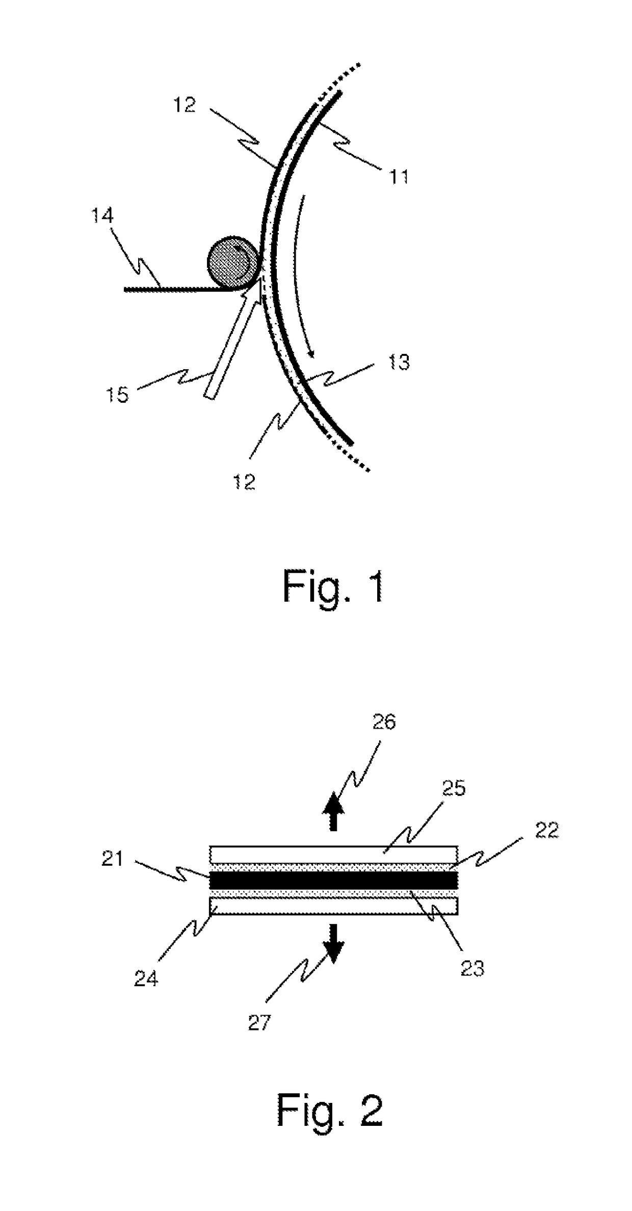
[0043]As has been stated above, the object of the presently disclosed embodiment is to enable the joining, via welding, of a first element, not formed of a thermoplastic material, an element made of polymer material or else an element made of metal for example, to a second element made of thermoplastic composite material.

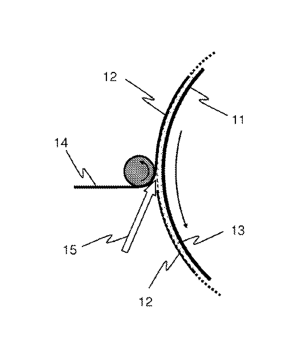
[0044]It is particularly, but not exclusively, suitable for producing a fluid tank comprising an inner envelope, or liner, intended to contain the fluid in a leaktight manner, covered by a mechanically strong wall made of thermoplastic composite material formed directly around the liner, by the filament winding technique for example, the inner envelope and the mechanically strong protective wall, of different natures, being joined by welding to one another.

[0045]In the remainder of the description, the features of the process according to the presently disclosed embodiment are described by way of an implementation example, illustrated by FIG. 1, relating to the prod...


PUM

PropertyMeasurementUnit
particle sizeaaaaaaaaaa
thicknessaaaaaaaaaa
thicknessaaaaaaaaaa

Abstract

The invention concerns a method for producing, by welding, a link between an element made from any material, for example metal, and an element made from a thermoplastic-matrix composite material, the second element being produced by depositing a textile yarn pre-impregnated with a thermoplastic material on the surface of the first element. The method mainly includes an operation consisting of producing an interface coating consisting of an epoxy resin filled with a thermoplastic material powder, coating the surface of the element made from any material with same, and leaving the coating to polymerize. It next includes an operation consisting simultaneously of forming the second element and welding same to the coating deposited on the surface of the first element by locally heating the two elements, when depositing the pre-impregnated textile on the first element.

Description

CROSS REFERENCE TO RELATED APPLICATIONS[0001]This application is the National Stage of International Application No. PCT / EP2014 / 056030, having an International Filing Date of 26 Mar. 2014, which designated the United States of America, and which International Application was published under PCT Article 21(s) as WO Publication No. 2014 / 161753 A1, and which claims priority from, and the benefit of French Application No. 1352986, filed 3 Apr. 2013, the disclosures of which are incorporated herein by reference in their entireties.BACKGROUND[0002]1. Field[0003]The presently disclosed embodiment relates to the general field of producing tanks made of high-performance composite materials, intended for storing pressurized fluids.[0004]The presently disclosed embodiment applies in particular to tanks made of thermoplastic matrix composite materials, but may be applied to tanks made of composite materials comprising other types of matrices (radiation-polymerizable, thermosetting, etc. matrice...

Claims


Application Information

Patent Timeline
Patent Type & Authority Patents(United States)
IPC IPC(8): B32B37/00B29C65/02B29C65/00F16J12/00F17C1/00B29C65/48B29C63/24B29C53/60B29L31/00
CPCB29C65/022B29C66/1122B29C66/532F16J12/00F17C1/00Y02E60/321B29C53/602B29C63/24B29C65/02B29C65/4815B29C65/4865B29C66/69B29C66/71B29C66/7392B29C66/7394B29C66/83411B29L2031/7156B29L2031/7172F17C2201/0104F17C2203/0604F17C2203/0619F17C2203/0636F17C2203/0663F17C2209/22F17C2209/221F17C2209/232F17C2221/012F17C2221/033F17C2221/08F17C2223/0161F17C2223/035B29K2077/00Y02E60/32
Inventor LEBRUN, HELENEDEFOORT, BRIGITTELACOUR, DOMINIQUEMENOCHET, AUDREY
Owner ARIANEGRP SAS
Why Eureka
Try Eureka