Solar cell

a solar cell and solar cell technology, applied in the field of solar cells, can solve the problems of reducing achieve the effect of improving the effective area of the solar cell, and improving the photoelectric conversion efficiency of the solar cell

Inactive Publication Date: 2018-04-10
LG INNOTEK CO LTD
View PDF31 Cites 0 Cited by
  • Summary
  • Abstract
  • Description
  • Claims
  • Application Information

AI Technical Summary

Benefits of technology

[0013]According to the solar cell of the embodiment, the grid electrode is formed by using the transmissive conductive material, so that current collection characteristics can be improved without reducing the effective area of the solar cell. Thus, the photoelectric conversion efficiency of the solar cell can be effectively improved. In addition, the grid electrode may serve as the anti-reflection wall, so that the photoelectric conversion efficiency of the solar cell may be more improved. The grid electrode may be formed by using the transparent conductive material or a metal layer having a thin thickness. If a part of the grid electrode, which is formed by using the transparent conductive material, is integrally formed with the second electrode layer, the manufacturing process can be simplified and the junction characteristic can be improved. In addition, if a part of the grid electrode is formed by using the metal layer, the current collection characteristic can be more improved by the metal layer having the superior electric conductivity.

Problems solved by technology

However, a region where the opaque grid is located may become a dead zone that blocks transmission of the solar light, so the effective area of the solar cell may be reduced.

Method used


Image

  • Solar cell
  • Solar cell
  • Solar cell

Examples


first embodiment

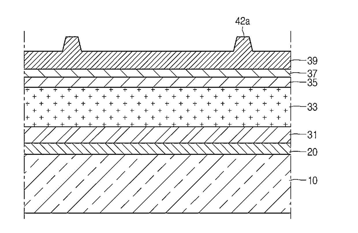
[0021]FIG. 1 is a schematic sectional view showing a solar cell according to the

[0022]Referring to FIG. 1, the solar cell 100 according to the embodiment includes a substrate 10 on which a first electrode 31, a light absorbing layer 33, a second electrode layer 39 and a grid electrode 42 are sequentially formed. In addition, the solar cell 100 may further include a barrier layer 20, a buffer layer 35 and a high-resistance buffer layer 37. The structure of the solar cell 100 will be described below in more detail.

[0023]The substrate 10 has a plate shape and supports the first electrode layer 31, the light absorbing layer 33 and the second electrode layer 39 formed thereon. The substrate 10 may include an insulator, such as glass or plastic. For instance, the substrate 10 may include soda lime glass. However, the embodiment is not limited thereto. For instance, the substrate 10 may include a metallic substrate. That is, the substrate 10 may be formed by using a rigid material or a fle...

second embodiment

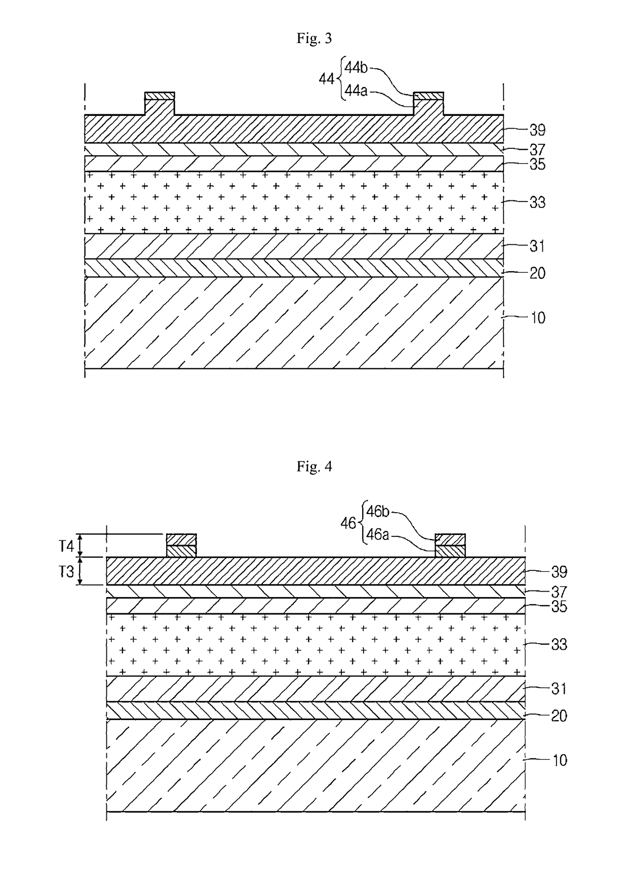
[0050]FIG. 3 is a schematic sectional view showing a solar cell according to the

[0051]Referring to FIG. 3, the grid electrode 44 according to the second embodiment includes a first layer 44a formed by using a material the same as that of the second electrode layer 39, and a second layer 44b formed by using a material having resistance lower than that of the first layer 44a.

[0052]For instance, the first layer 44a may be formed by using a transparent conductive material, such as aluminum-doped zinc oxide (AZO), fluorine-doped tin oxide (FTO), gallium-doped zinc oxide (GZO), or boron-doped zinc oxide (BZO). In addition, the second layer 44b may be formed by using a metal, such as Ni, Ag, Pt, Au or an alloy thereof. The second layer 44b has a thin thickness to allow light to pass therethrough. That is, the second layer 44b may have light transmittance although the second layer 44b is formed by the metal.

[0053]As described above, since the grid electrode 44 has the first layer 44a inclu...

third embodiment

[0056]FIG. 4 is a schematic sectional view showing a solar cell according to the

[0057]Referring to FIG. 4, a grid electrode 46 according to the third embodiment can be formed by sequentially laminating first and second metal layers 46a and 46b, which are different from each other, on the second electrode layer 39.

[0058]For instance, the first metal layer 46a may include Ni, Ag, Pt or an alloy thereof and the second metal layer 46b may include Au. The first and second metal layers 46a and 46b have a thin thickness to allow light to pass therethrough, so the grid electrode may have the light transmittance and conductivity.

[0059]According to the third embodiment, the grid electrode 46 is formed by using the metal, so that the resistance can be more reduced. Thus, the photoelectric conversion efficiency of the solar cell can be more improved.

[0060]When taking the resistance and transmittance of the grid electrode 46 into consideration, a ratio (T4 / T3) of a thickness T4 of the grid elect...


PUM


Abstract

A solar cell according to the embodiment includes a substrate; a first electrode layer on a substrate; a light absorbing layer on the first electrode layer; a second electrode layer including a transmissive conductive material on the light absorbing layer; and a grid electrode including a transmissive conductive material on the second electrode layer.

Description

CROSS-REFERENCE TO RELATED APPLICATIONS[0001]This application is the U.S. national stage application of International Patent Application No. PCT / KR2011 / 003118, filed Apr. 27, 2011, which claims priority to Korean Application No. 10-2010-0097471, filed Oct. 6, 2010, the disclosures of each of which are incorporated herein by reference in their entirety.TECHNICAL FIELD[0002]The disclosure relates to a solar cell.BACKGROUND ART[0003]Recently, as energy consumption is increased, a solar cell has been developed to convert solar energy into electrical energy. In such a solar cell, the improvement of the photoelectric conversion efficiency is an important factor.[0004]In order to improve the photoelectric conversion efficiency, an opaque grid made from a metal is formed at a front surface of the solar cell. According to this method, the current collection characteristics can be improved because the grid has superior electric conductivity. However, a region where the opaque grid is located ...

Claims


Application Information

Patent Timeline
Patent Type & Authority Patents(United States)
IPC IPC(8): H01L31/0224H01L31/18H01L31/0468H01L31/0749
CPCH01L31/022433H01L31/022425H01L31/022466H01L31/022483H01L31/0468H01L31/0749H01L31/1884H01L31/022491Y02E10/541
Inventor BAE, DO WONPAK, HISUN
Owner LG INNOTEK CO LTD
Why Eureka
Try Eureka