High efficiency control system for the conversion of electrical energy to thermal energy

a control system and high efficiency technology, applied in the direction of transmission systems, railway braking systems, electrical equipment, etc., can solve the problems of significant voltage transient spikes, general unsuitability of mechanically switched unit resistor load stepping, and generate a rapid change in the temperature of the heater or the heater. to achieve the effect of reducing the switching transien

Active Publication Date: 2018-04-17
KELVIN THERMAL ENERGY INC
View PDF2 Cites 15 Cited by
  • Summary
  • Abstract
  • Description
  • Claims
  • Application Information

AI Technical Summary

Benefits of technology

[0017]In a preferred aspect, each control arrangement includes control logic for incrementally activating the controllers to dynamically increase or decrease loading of the energy storage system in a predetermined manner to reduce transients caused by connecting or disconnecting the separate loads to or from the energy storage system.
[0020]In a preferred aspect of the power generation system, a power management controller for the series of thermal storage units is used where the power management controller selectively activates the controllers in a predetermined manner to provide a power receiving transition period for the grid supply network that reduces switching transients produced by activating any of the controllers. Preferably the independent loads are each a series of thermal resistors distributed within the thermal storage body.

Problems solved by technology

Mechanically switched unit resistor load stepping is generally not suitable for cases where the resistive load needs to be switched on or off very rapidly to and from the electrical distribution source.
Once activated or deactivated, a mechanical switch or relay generally makes contact one or more times and at an unknown position in the phase of each line, which can lead to significant voltage transient spikes.
High rates of change in power when a load is suddenly connected at or near full power can generate a rapid change in the temperature of the heater or heaters.
This temperature change can accelerate the damage done by thermal shock and eventual device failure at one or more mechanically weakest connections or any electrical “hot spot.” The sudden power draw or removal coming from massive load switching can overwhelm and possibly damage the electrical motor / generators providing power to the grid.
The harmonics and sub-harmonics produced by such a power change can be significant enough to adversely affect portions of the grid (micro-blackouts or brownouts), particularly in distribution areas electrically “close” to the high power switched load or when the grid transmission equipment is near its load limit.
Variable voltage output PWM controllers can typically operate at about 89% efficiency with many models unable to achieve stable low output voltages, causing a typical lower limit of about 1% to 5% of rated output voltage.
If the load to be controlled is on the order of megawatts for high demand applications, even a loss of 2% source power reaching the load can result in very significant control electronics power consumption.
In addition to being wasteful, the resulting heat must be removed in continuous operation of the system.
For example, a 2% loss of a 1 MW load results in 20 KW that goes to the power control components and that can require large, expensive, and less reliable cooling to accomplish accurate load balancing.
In addition, the high frequency switching of PWM can introduce unwanted harmonics and some amount of phase shift to the input power source (AC Mains) due to the reactive (inductance, capacitance) circuit design that makes PWM possible.
These harmonics and phase shifts can be compensated for with a more sophisticated design, but at the expense of even lower output efficiency, in addition to more controller components and complexity.
However, mechanical contact switches generally cannot be turned on or off with sufficient speed or accuracy to avoid creating random transient excursions on the grid as the electrical switching occurs.
This effect can therefore lead to a series of overload failures that quickly overwhelms a power grid's ability to accommodate them in a controlled fashion, and can in some cases even escalate to become a serious brownout or blackout major portions of the grid, as was recently demonstrated by the blackout from Phoenix to San Diego.
The nullification of reactive loading can result in a power factor at or near 1.0, meaning that little or none of the energy received for storage is reflected by reactive components back onto the grid.
Since the storage power load can be variable, the use of fixed reactive compensation is generally precluded.

Method used


Image

  • High efficiency control system for the conversion of electrical energy to thermal energy
  • High efficiency control system for the conversion of electrical energy to thermal energy
  • High efficiency control system for the conversion of electrical energy to thermal energy

Examples


Embodiment Construction

[0044]In some example applications in which implementations of the current subject matter can provide benefits, a high power AC source can be the distribution level (currently defined as 70,000 Volts or less) of electrical transmission utility, or an independent generating station, micro-grid, or other managed electrical power distribution network. The thermal energy may then be utilized as part of energy storage, manufacturing processes, or other useful purposes in which precision control of at least one of heat flow and temperature is desired. The amount of energy converted can be varied in scalable steps for the precision desired from zero to one hundred percent of the attached load, and can be capable of delivering different amounts of power to different segments of a load or separate loads, depending on the number of resistive load elements and their distribution amongst multiple load controller modules connected to one or more master load management controllers.
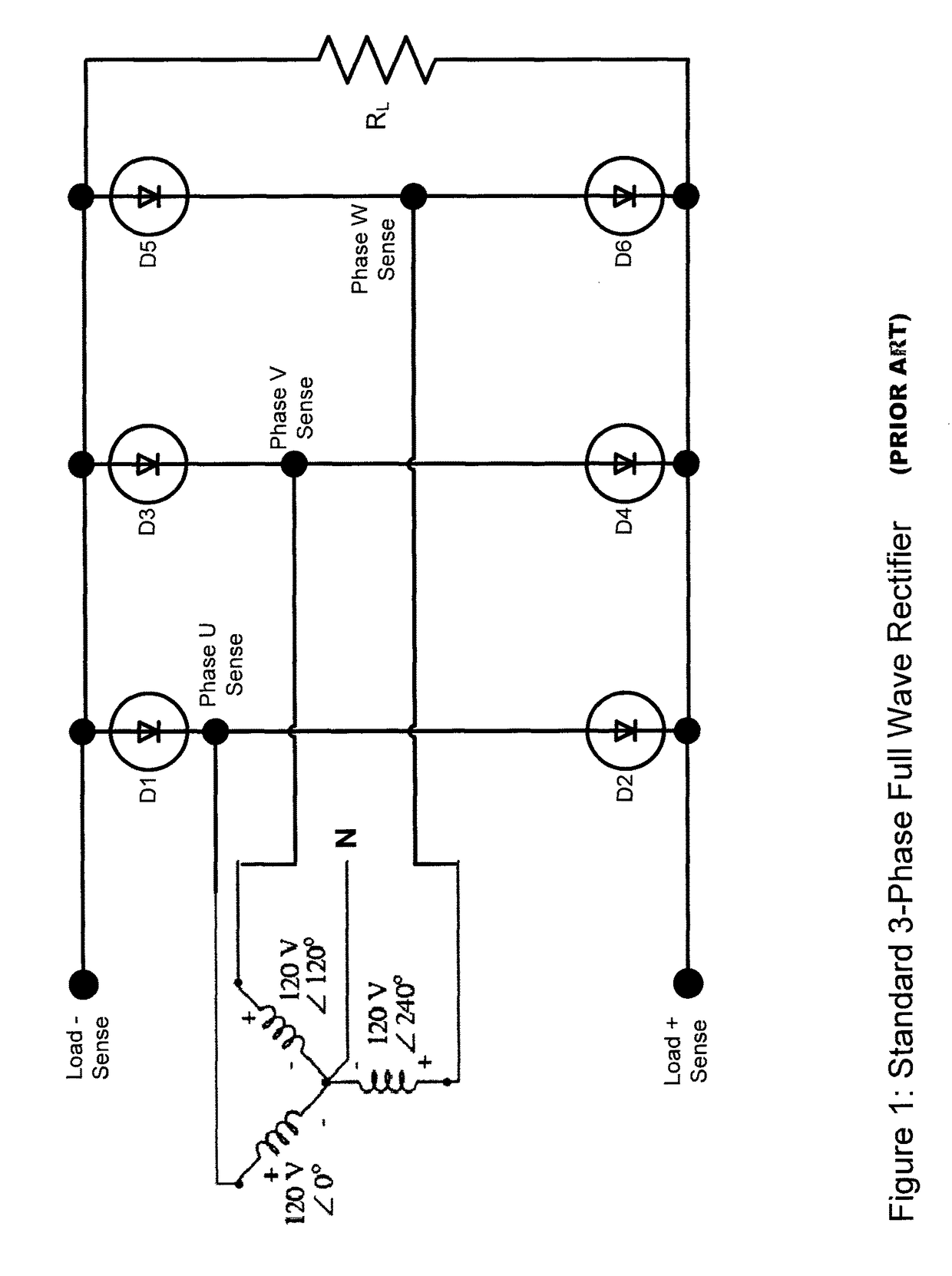
[0045]FIG. 1 is...


PUM


Abstract

An improved control arrangement is used in a high power rectifier and comprises two or more power controllers ganged together in parallel. Each power controller rectifies an AC voltage signal using zero voltage crossing switching to produce a binary switched signal and each power controller is connected to an independent connectable load. Each power controller includes a fast acting binary power switch that selectively connects the respective independent connectable load to the rectified AC voltage signal. The control arrangement selectively activates the power controllers to define a desired connected load. This high power rectifier and control arrangement is advantageously used to provide fast up down power regulation to a grid by selective storage of thermal energy and deriving power from the thermal energy storage system to add fill in power to the grid.

Description

[0001]This application claims priority from U.S. Provisional Application Ser. No. 61 / 624,182 filed Apr. 13, 2012 and is incorporated herein by reference.FIELD OF THE INVENTION[0002]The subject matter described herein generally relates to conversion of electrical energy from an alternating current (AC) high power source to direct current, preferably used as an input for an energy storage system.BACKGROUND OF THE INVENTION[0003]Dynamic braking has been used in railroad and transit applications to convert braking energy to heat or electrical power, for example by use of one or more electric traction motors of a railroad vehicle for electrical power generation when braking. Such electro-dynamic braking generally significantly lowers the wear of friction-based braking components. In dynamic braking, resistors can be provided to dissipate braking energy, typically by engaging one or more resistors within a bank (a collection of resistors) or one or more entire banks of resistors. In the a...

Claims


Application Information

Patent Timeline
Patent Type & Authority Patents(United States)
IPC IPC(8): H02J15/00B60L8/00B60L11/18B60L15/00H02M7/217H02M7/06B60T13/58B60T1/10B61H9/06H02J3/00B60L1/04B60L3/00
CPCH02J15/00B60L3/0092B60L8/003B60L11/1842B60L15/007B60T1/10B60T13/586B61H9/06H02M7/066H02M7/2176B60L1/04Y10T307/685B60L2200/26B60L2210/30Y02E60/721Y02T10/645Y02T10/7005Y02T10/7072Y02T10/7083Y02T10/7241Y02T90/121Y02T90/127Y02T90/128Y02T90/14Y02T90/163Y04S10/126B60L55/00Y02E60/00Y02T10/64Y02T10/72H02M1/0085Y02T10/70Y02T90/12Y02T90/16
Inventor PIETSCH, ANTONLYNCH, GEORGESUTHERLAND, STEPHEN B.
Owner KELVIN THERMAL ENERGY INC
Why Eureka
Try Eureka