Dynamic memory management

a memory management and dynamic technology, applied in the field of dynamic memory management, can solve the problems of large information storage capacity, large amount of power, bulky and large, and memory systems are typically either very expensive or require too much power, so as to avoid loss of stored information

Inactive Publication Date:
View PDF15 Cites 10 Cited by
  • Summary
  • Abstract
  • Description
  • Claims
  • Application Information

AI Technical Summary

Benefits of technology

[0008]In a preferred embodiment, the present invention provides a method for reducing the supply voltage and reducing the frequency of accesses to volatile memory stored in battery-powered devices. Further, the present invention provides a method for partitioning volatile memory chips to reduce the number of volatile memory chips needed to store a given set of information. Further, the present invention provides a method for determining a minimal refresh rate to reliably maintain information on volatile memory chips during accesses.
[0011]In another broad respect, the present invention is directed to a device comprising a processor, a dynamic memory adapted to store information, and a program adapted to be executed by the processor to determine the minimum refresh rate for the dynamic memory, wherein the dynamic memory must be refreshed at at least the determined minimum refresh rate to avoid loss of stored information. In one embodiment, the device further comprises a clock signal, wherein the dynamic memory is adapted to undergo a refresh cycle responsively to the clock signal; wherein the dynamic memory is adapted to be used in one of at least two device modes, the at least two device modes comprising (a) power up mode and (b) power down mode; and wherein, when the dynamic memory is used in a device power down mode, the rate of the clock signal causes the dynamic memory to be refreshed at approximately a determined minimum refresh rate. In another embodiment, a determined minimum refresh rate corresponds to a normal operating temperature range. In other embodiments, when the dynamic memory is used in a device power up mode, the actuation rate of the clock signal causes the dynamic memory to be refreshed at approximately the a determined minimum refresh rate; wherein a clock signal causing the dynamic memory to undergo a read cycle prevents occurrence of a refresh cycle; and wherein a clock signal causing the dynamic memory to undergo a write cycle prevents occurrence of a refresh cycle.
[0013]In another broad respect, the present invention is directed to a method comprising the steps of executing a read cycle on a dynamic memory responsively to receiving a read instruction and a clock signal; executing a write cycle on the dynamic memory responsively to receiving a write instruction and the clock signal; executing a refresh cycle, thereby refreshing the dynamic memory, responsively to receiving the clock signal, not receiving the read instruction, and not receiving the write instruction; and actuating the clock signal asynchronously sufficiently frequently such that the dynamic memory does not lose its stored information.
[0016]In another embodiment, the method further comprises the steps of executing a read cycle on a dynamic memory responsively to receiving a read instruction and a clock signal; executing a write cycle on the dynamic memory responsively to receiving a write instruction and the clock signal, wherein executing a refresh cycle, to refresh the dynamic memory responsively to receiving the clock signal comprises the step of executing a refresh cycle, to refresh the dynamic memory responsively to receiving the clock signal in the absence of the read instruction and absence of the write instruction; and actuating the clock signal asynchronously sufficiently frequently such that the dynamic memory does not lose its stored information.

Problems solved by technology

Battery-powered electronic devices such as digital music players and digital cameras typically require significant information storage capacity, and must maintain information during periods of time when the device is in a powered down state.
These memory systems however, typically are either very expensive or require too much power to make them viable for inexpensive battery-powered devices.
For example, hard drives and floppy disks are inexpensive on a cost per megabyte basis, but are both bulky and require large amounts of power.
Flash memory is expensive, but is compact and reliable.
Volatile memory has not been considered a viable solution because of the high power consumption rate typically associated with the need for constant power to maintain information reliably.

Method used


Image

  • Dynamic memory management
  • Dynamic memory management
  • Dynamic memory management

Examples


Embodiment Construction

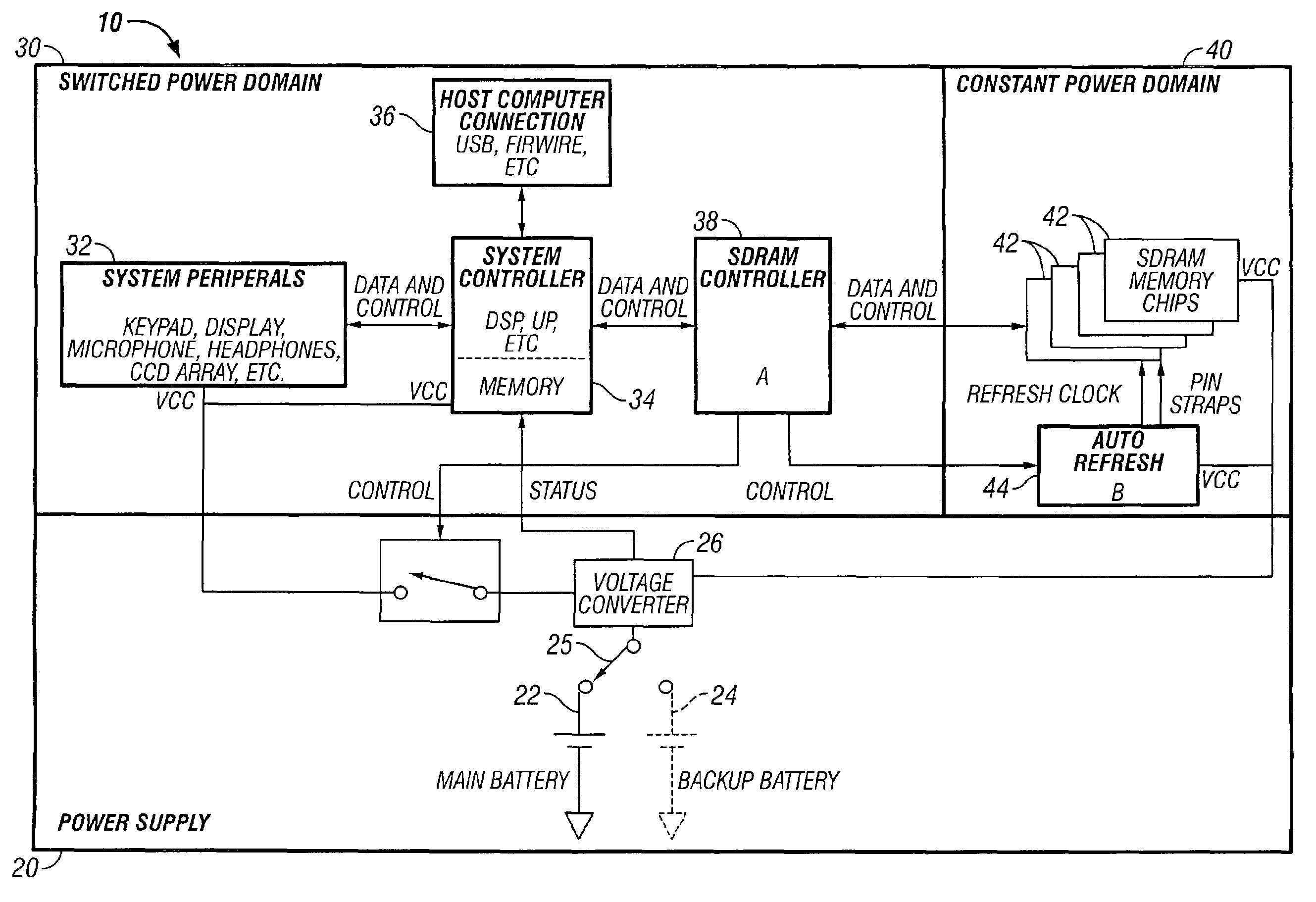
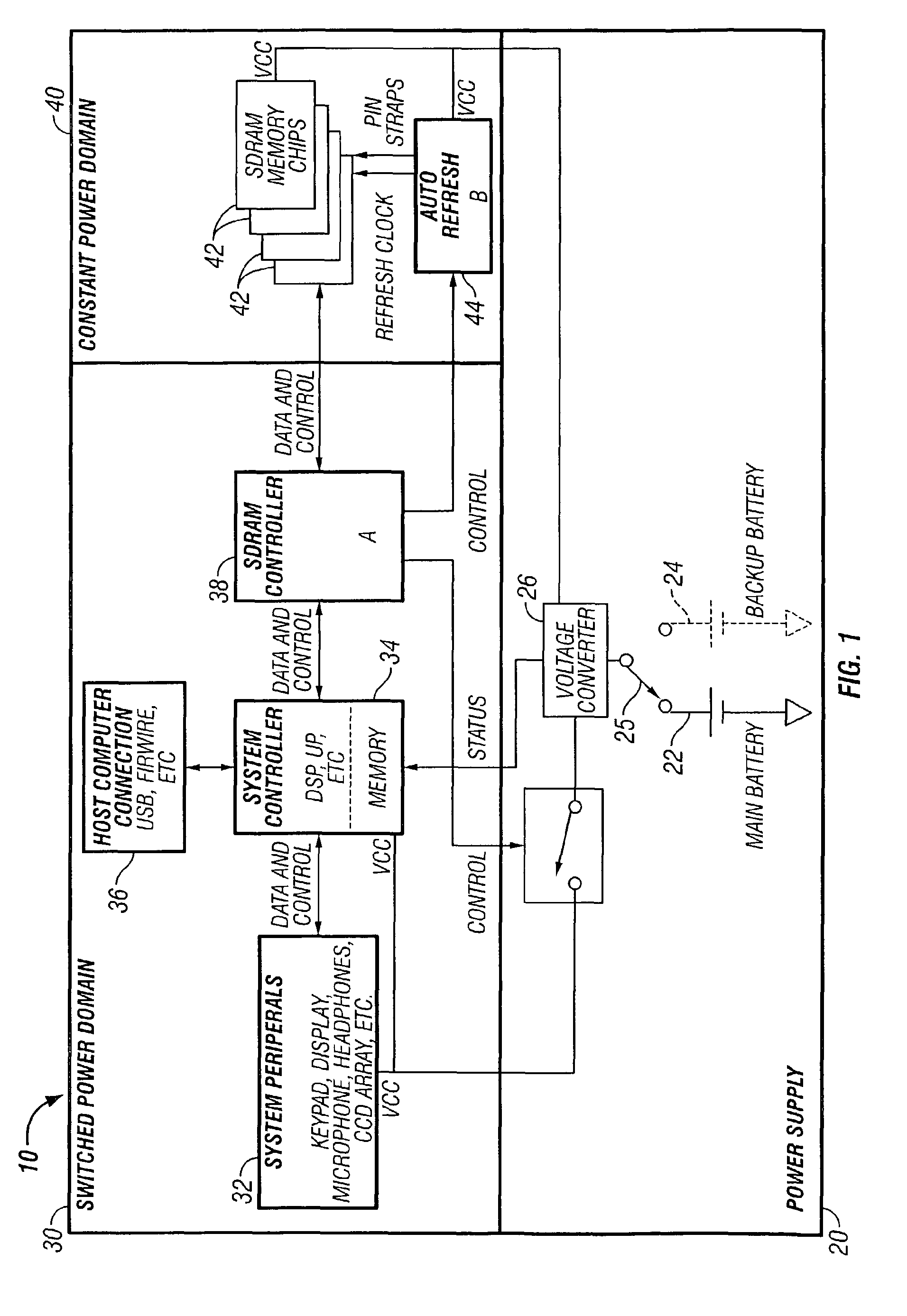
[0022]The present invention solves the shortcomings of previous battery-powered device information storage systems with methods and systems for storing information in volatile memory. The discussion throughout this application of “SDRAM” applies equivalently to other types of dynamic volatile memory.

[0023]The use of inexpensive volatile memory for the non-volatile storage of information in battery-powered devices provides the power, size, and reliability advantages of non-volatile memory, but reduces the cost. A cost-effective dynamic memory type currently available is Synchronous Dynamic Random Access Memory (SDRAM). Other types of DRAM are also dynamic, and the scope of the present invention, as claimed, is not limited to any particular type of volatile memory. Due to the use of SDRAM memory chips in personal computers, this memory type is available in high volumes at low cost. In order for SDRAM to be considered a viable replacement for non-volatile memory systems such as flash m...


PUM


Abstract

In a method, system and apparatus for management of dynamic memory in battery-powered devices, information is stored in dynamic memory, such as SDRAM chips. Chip partitioning minimizes the number of chips requiring power, minimum refresh rates reduce the power needed to maintain information, and a threshold for determining when to power down a battery powered device are used to maximize battery life.

Description

BACKGROUND OF THE INVENTION[0001]1. Field of the Invention[0002]The present invention relates to the field of dynamic memory management. In particular, the present invention relates to hardware and software methods to manage the use of dynamic memory in devices requiring low power consumption, such as battery-powered devices.[0003]2. Description of Related Art[0004]Battery-powered electronic devices such as digital music players and digital cameras typically require significant information storage capacity, and must maintain information during periods of time when the device is in a powered down state. Current battery-powered electronic devices address these needs with various forms of non-volatile memory, such as solid-state flash memory, hard drives, floppy disks, etc. These memory systems however, typically are either very expensive or require too much power to make them viable for inexpensive battery-powered devices. For example, hard drives and floppy disks are inexpensive on a...

Claims


Application Information

Patent Timeline
Patent Type & Authority Patents(United States)
IPC IPC(8): G11C11/406G06F1/04G11C7/22G11C8/18G11C11/4076G06F13/16
CPCG06F13/1689G11C11/406G11C11/40611G11C2211/4061Y02D10/00
Inventor STIMAK, MARCBROWN, TERRY C.MINNICK, MIKE
Why Eureka
Try Eureka