Hydration, pressure swing adsorption and deep cooling combined process for separating ethene cracking gas

A combined process and pressure swing adsorption technology, which is applied in the purification/separation of hydrocarbons, hydrocarbons, hydrocarbon cracking and hydrocarbon production, etc., can solve the problems of no more reports, reduce production energy consumption and cost input, and reduce The cooling load at the top of the tower and the effect of reducing the overall energy consumption

Inactive Publication Date: 2008-07-23
CHINA UNIV OF PETROLEUM (BEIJING)
View PDF3 Cites 0 Cited by
  • Summary
  • Abstract
  • Description
  • Claims
  • Application Information

AI Technical Summary

Problems solved by technology

[0005] The current research and application status of hydrate technology is more about gas storage and transpor

Method used


Image

  • Hydration, pressure swing adsorption and deep cooling combined process for separating ethene cracking gas

Examples


Embodiment 1

[0029] Example 1. Analysis of the separation effect and energy consumption of ethylene cracking gas in the combined process of hydration separation + pressure swing adsorption separation + cryogenic separation

[0030] In this embodiment, the simulated ethylene cracking gas is separated according to the combined process flow of the present invention, the separation effect data is recorded, and the heat energy consumption in the process is analyzed.

[0031] Simulated ethylene cracking gas (feed gas) stream composition (mol%):

[0032] h 2 , 19.85%; CH 4 , 42.78%; C 2 h 4 , 33.78%; C 2 h 6 , 2.41%; C 3 h 6 , 0.35%.

[0033] Specific process flow:

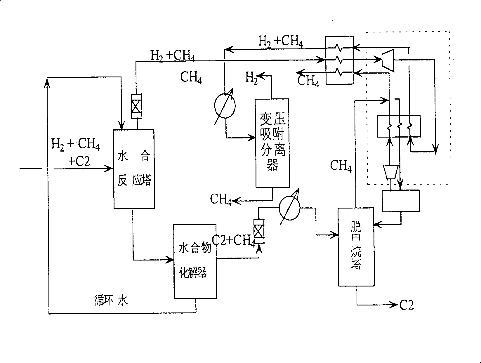
[0034] The cracked gas stream to be separated (the pressure of the cracked gas at this time is about 3.6 MPa) is first sent into the hydration reactor, which is a hydration reaction tower capable of multi-stage separation in this embodiment. The operating conditions of the hydration reaction tower are: temperature 1°C, pres...

Embodiment 2

[0049] Embodiment 2, the single-stage hydration separation of the water liquid separation ethylene cracking gas containing SDS (500ppm)

[0050] Hydration reaction conditions: T=275.15K, P=3MPa, gas-water volume ratio is 75:1.

[0051] Experimental method: The cracked gas mixture to be separated and the water-containing liquid are contacted in a high-pressure reactor to form hydrates. During the reaction process, the reaction temperature and pressure were kept constant, and when the reaction reached equilibrium, the composition of the gas phase and the composition of the gas released after the dissolution of the hydrate were analyzed respectively.

[0052] The composition of the gas released after the hydrate is dissolved is the dry basis composition of the hydrate phase (the composition of the gas after deducting the amount of water).

[0053] Table 1. Single-stage hydration separation effect of water-liquid separation of ethylene cracking gas containing SDS (500ppm)

[005...

Embodiment 3

[0055] Embodiment 3, the single-stage hydration separation of ethylene cracking gas separation when the water-containing liquid adopts the emulsion of water+diesel

[0056] Hydration reaction conditions: T=274.15K, P=5MPa, oil-water volume ratio is 2:1, emulsifier Span 20 is used to make a water-in-oil emulsion system, and the gas-liquid volume ratio entering the hydration reaction tower is 75:1;

[0057] The experimental method is the same as in Example 2.

[0058] Table 2. The single-stage hydration separation effect of separating ethylene cracking gas when the water-containing liquid adopts water+diesel oil emulsion

[0059]


PUM


Abstract

The present invention proposes one method of separating ethylene cracking gas, is one combined separation process including hydrating separation, cryogenic separation and PSA separation, and aims at applying new hydrating separation process in the separation of ethylene cracking gas. First, reaction condition is controlled for the C2 component in the cracked gas to form hydrate prior and to be separated. Then, the cold produced by the expanding methane and hydrogen flow is used as the cold source for the methane eliminating tower, and PSA separation is combined to realize the separation of hydrogen, methane and C2 component ultimately. The present invention has no stage-by-stage condensation steps and cold casing and thus lowered cold load of the methane eliminating tower.

Description

technical field [0001] The invention relates to a separation process of ethylene cracking gas, in particular to a combined process flow for separating ethylene cracking gas by combining a hydration separation process, freezing separation and pressure swing adsorption separation process, and belongs to the chemical technology. Background technique [0002] As a pillar industry of the petrochemical industry, the ethylene industry has always played an important role in the national economy. With the development and requirements of various aspects, most of the existing ethylene plants are under the pressure of capacity expansion and efficiency enhancement. The most complicated part of the ethylene cracking and separation process is the cryogenic demethanization section, especially the cryogenic demethanizer, which is commonly used at present, is the bottleneck of the entire device's capacity expansion and efficiency enhancement. [0003] In the separation process of cryogenic d...

Claims


Application Information

Patent Timeline
IPC IPC(8): C07C7/00C07C9/04C07C11/04C07C4/02
Inventor 陈光进王秀林郭绪强孙长宇马庆兰
Owner CHINA UNIV OF PETROLEUM (BEIJING)
Why Eureka
Try Eureka