Check patentability & draft patents in minutes with Patsnap Eureka AI!

Measuring circuit for measuring supersonic wave level meter transit time

A time-of-flight and measurement circuit technology, applied in the field of measurement circuits, can solve problems such as measurement errors, and achieve the effects of simplifying system design, improving flexibility, and clear structure

Inactive Publication Date: 2009-01-14
SOUTHEAST UNIV
View PDF2 Cites 0 Cited by
  • Summary
  • Abstract
  • Description
  • Claims
  • Application Information

AI Technical Summary

Problems solved by technology

[0006] Since the speed of sound is greatly affected by the temperature, density, and pressure of the propagation medium air, the general method that can be used is temperature compensation for the speed of sound, but there is no ideal compensation method for the change of sound speed caused by air density and pressure, so it is still necessary to measure the speed of sound. There are some errors,

Method used


Image

  • Measuring circuit for measuring supersonic wave level meter transit time
  • Measuring circuit for measuring supersonic wave level meter transit time
  • Measuring circuit for measuring supersonic wave level meter transit time

Examples


Embodiment Construction

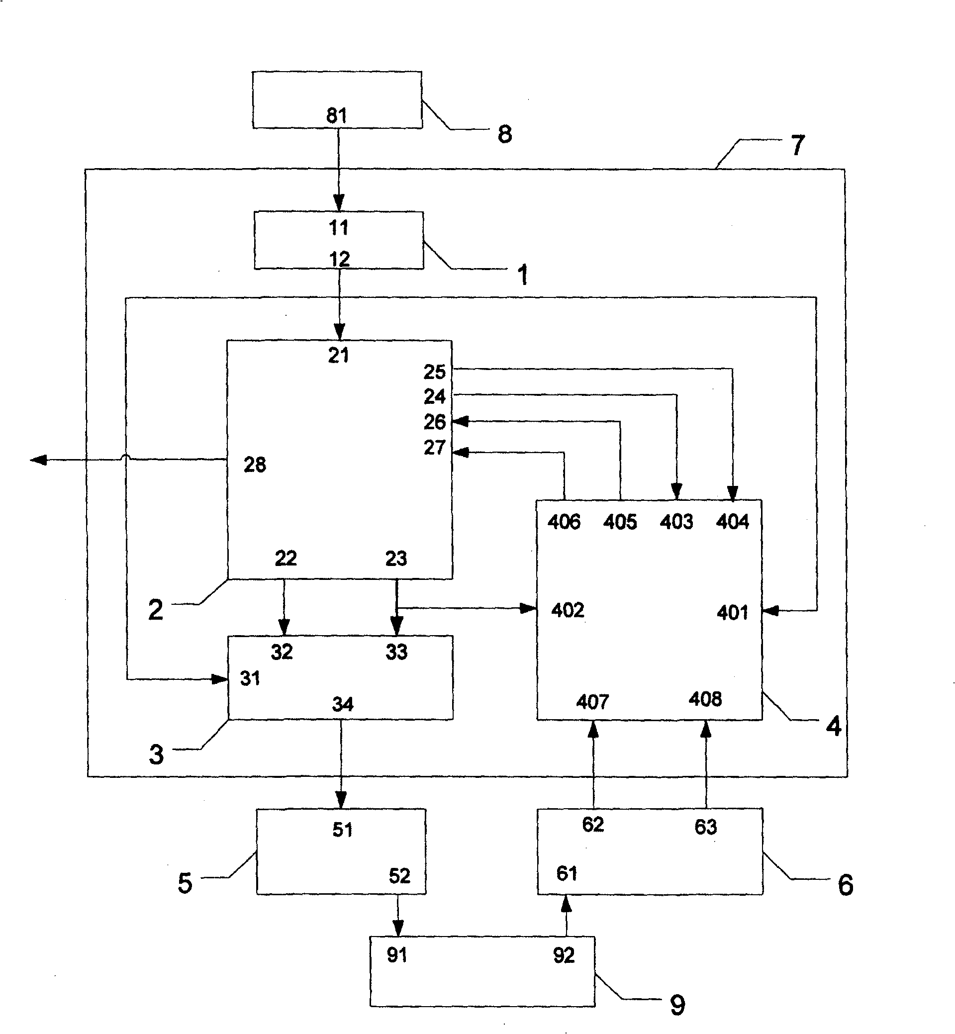
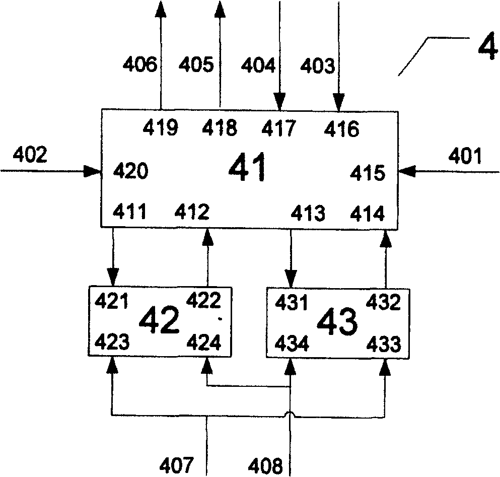
[0018] A measurement circuit for measuring the transit time of an ultrasonic level measuring instrument, comprising a transmitting power amplification circuit module 5 and an echo amplification comparison circuit module 6, the measurement circuit also includes an FPGA module 7, and the FPGA module 7 is controlled by a soft-core microcontroller Module 2, ultrasonic emission control module 3 and ultrasonic reception control module 4 are composed, wherein the clock input end 21 of the soft-core microcontroller module 2, the clock input end 31 of the ultrasonic emission control module 3 and the clock input end of the ultrasonic reception control module 4 401 are connected together, input the clock frequency at the same time, the clock frequency is not lower than 50 MHz and not higher than 200 MHz, the pulse control signal output terminal 22 and the pulse emission start signal output terminal 23 of the soft-core microcontroller module 2 are respectively Connect with the pulse contro...


PUM


Abstract

The utility model discloses a circuit for measuring the transmit time of a ultrasonic level transmitter, comprising a transmit power amplifying circuit module (5) and a echo amplifying comparison circuit module (6) and a FPGA module (7), which is characterized in that the utility model is embedded into a soft core microcontroller with field programmed gate array Cyclone EP1C6Q240,multiplies the input signal of low-frequency active crystal oscillator to 50MHz as the system clock with the phase locked loop and frequency multiplier circuit (The operation frequency of the whole FPGA system is 50 MHz), write ultrasonic transmitting control logic and ultrasonic receiving control logic with Verilog language. The measurement of ultrasonic transmitting time is realized by the FPGA hardware completely, so that the measuring resolution is improved to 20ns.

Description

technical field [0001] The invention relates to a measuring circuit for measuring time, in particular to a measuring circuit for measuring the transit time of an ultrasonic level measuring instrument. Background technique [0002] The measurement principle of the ultrasonic liquid level / level gauge is as follows: the ultrasonic wave emitted by the ultrasonic transducer (sensor) encounters the phase interface of the measured material and then reflects (echo), and the trigger pulse time of the ultrasonic transducer (sensor) is measured The echo generated by the ultrasonic wave meeting the measured liquid level / level interface returns to the arrival time; the difference between the two moments is called the "transit time" of ultrasonic measurement. From the transit time and the sound velocity of the sound wave in the transmission medium, the measured liquid level / level value can be easily calculated. [0003] Ultrasonic liquid level / level gauge, the key to improving the measur...

Claims


Application Information

Patent Timeline
Patent Type & Authority Patents(China)
IPC IPC(8): G01F23/296G01S15/08
Inventor 周杏鹏芮正新
Owner SOUTHEAST UNIV
Features
  • R&D
  • Intellectual Property
  • Life Sciences
  • Materials
  • Tech Scout
  • Unparalleled Data Quality
  • Higher Quality Content
  • 60% Fewer Hallucinations
Learn More