
A crossed combined dual cycle grating for quanta trap infrared detector

An infrared detector and cross-combination technology, applied in the field of gratings, can solve problems such as poor response uniformity, achieve the effects of improving response uniformity, improving coupling efficiency, and avoiding astigmatism

Active Publication Date: 2009-02-25
THE 13TH RES INST OF CHINA ELECTRONICS TECH GRP CORP
View PDF3 Cites 2 Cited by
  • Summary
  • Abstract
  • Description
  • Claims
  • Application Information

AI Technical Summary

Problems solved by technology

But the response uniformity on the entire surface is not very good, and when the size of the grating hole is small, it is relatively limited by the width of the photolithography line

Method used


Image

  • A crossed combined dual cycle grating for quanta trap infrared detector
  • A crossed combined dual cycle grating for quanta trap infrared detector
  • A crossed combined dual cycle grating for quanta trap infrared detector

Examples


Embodiment Construction

[0030] Below in conjunction with accompanying drawing, the present invention is described in further detail:

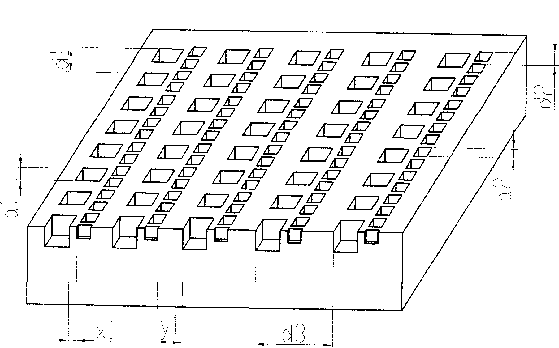
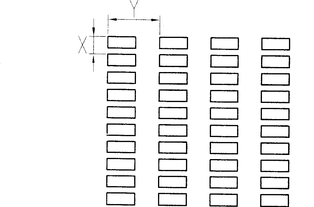
[0031] The structure and parameter distribution of the grating in the present invention are as Figure 5 , 6 as shown, figure 2 It is a schematic diagram of the three-dimensional structure of the grating of the present invention.

[0032] The invention includes gratings of two sizes responding to different wavelengths. The grating holes of the two sizes are arranged in rows and then crossed in sequence. One grating hole in an odd row and two grating holes in an even row form a "pin" shape.

[0033] The transverse dimension of a kind of cross-combined double-period grating used for quantum well infrared detectors according to the present invention is designed according to the single-period grating, and the calculation formula of its size parameter is d 1 =λ 1 / n;d 2 =λ 2 / n;a 1 =0.707d 1 ;a 2 =0.707d 2 ; h 1 =λ 1 / (3.2n); h 2 =λ 2 / (3.2n); The formula fo...


PUM


Abstract

The invention discloses a crossed combinational dual-period grating for quantum well infrared detector. By arranging two sizes of gates across, the invention responses to two wave bands and acquires the information of the two wave bands. The cross array makes a very good response uniformity of the new-type gates on the whole surface, and the two types of gates are distributed as the Chinese character 'pin', which makes the photolithography linewidth up to the maximum and thereby enhances the precision of photolithography patterns. The square gate hole is used to prevent astigmatism; the optimized parameter design enhances the coupling efficiency of the gates. The invention is applied to dual-color quantum well infrared detectors, is able to acquire the objective information more accurately in two wave bands simultaneously, more effectively inhibits the complicate background, and then enhances the detecting effect of objectives. The invention has the advantages of simple fabrication, low cost, and easy realization of mass and serial production.

Description

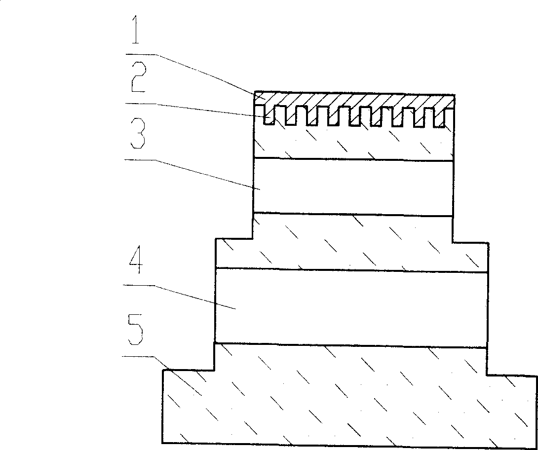
technical field [0001] The invention relates to a grating used in a double-color quantum well infrared detector. Background technique [0002] Quantum well infrared detector (abbreviated as QWIP in English) has the advantages of large area uniformity, radiation resistance, and easy monolithic integration of two-color or multi-color devices. It is the focus of infrared detector research at present. It has wide application prospects in industrial monitoring, medical and health, food industry and other fields. Its principle structure is as follows: figure 1 shown. It is a goal that people have been pursuing to develop a quantum well infrared focal plane array with high responsivity and detection rate and low price. Foreign research institutes have reported two-color, three-color and four-color quantum well infrared detectors (Quantum well infrared detectors are referred to as QWIP below). 640×512. Since the QWIP active area does not absorb the incident light component perpe...

Claims


Application Information

Patent Timeline
Patent Type & Authority Patents(China)
IPC IPC(8): H01L31/0232H01L31/18G02B5/18G02F1/35G03F7/00
CPCY02P70/50
Inventor 齐丽芳李献杰赵永林尹顺政蔡道民
Owner THE 13TH RES INST OF CHINA ELECTRONICS TECH GRP CORP
Learn More