Textile and non-woven cloth plasma surface treating device
A surface treatment device and plasma technology, applied in textiles and papermaking, fiber treatment, physical treatment, etc., can solve problems such as low efficiency, burning of fiber materials, uneven filamentary discharge, etc., and achieve current density and energy density Weaken, improve uniformity, improve wettability effects
- Summary
- Abstract
- Description
- Claims
- Application Information
AI Technical Summary
Problems solved by technology
Method used
Image
Examples
Embodiment 1
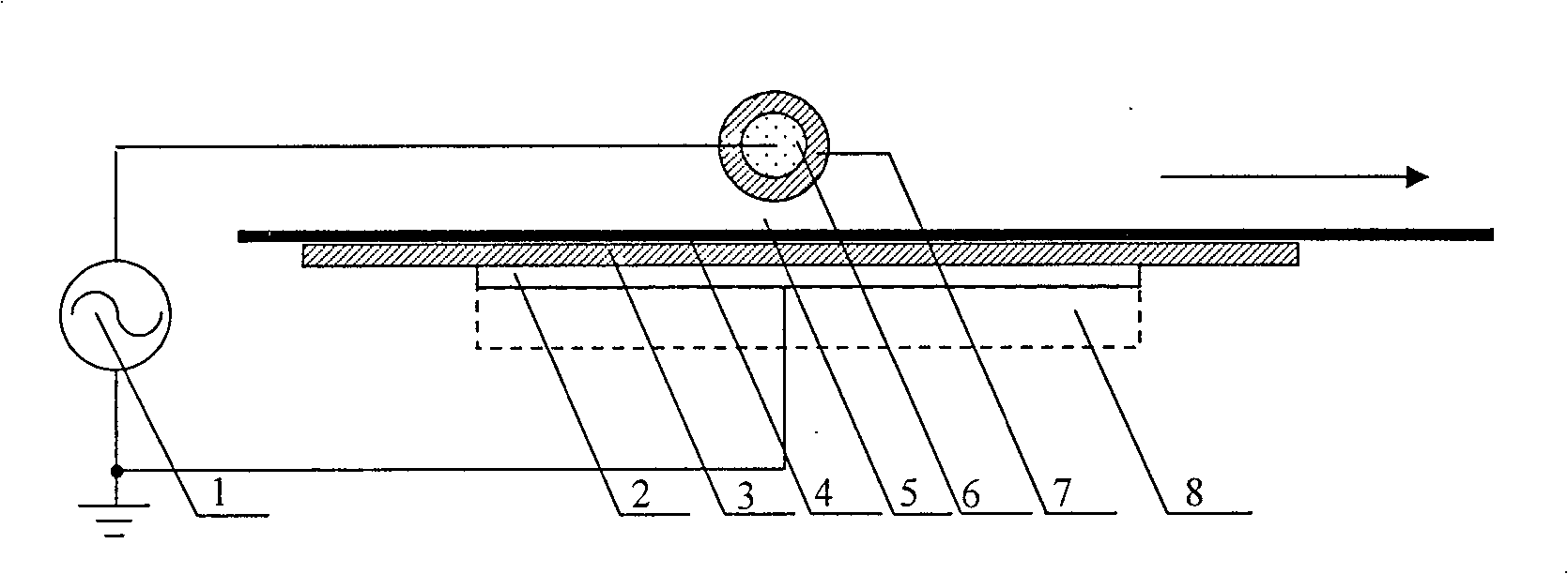
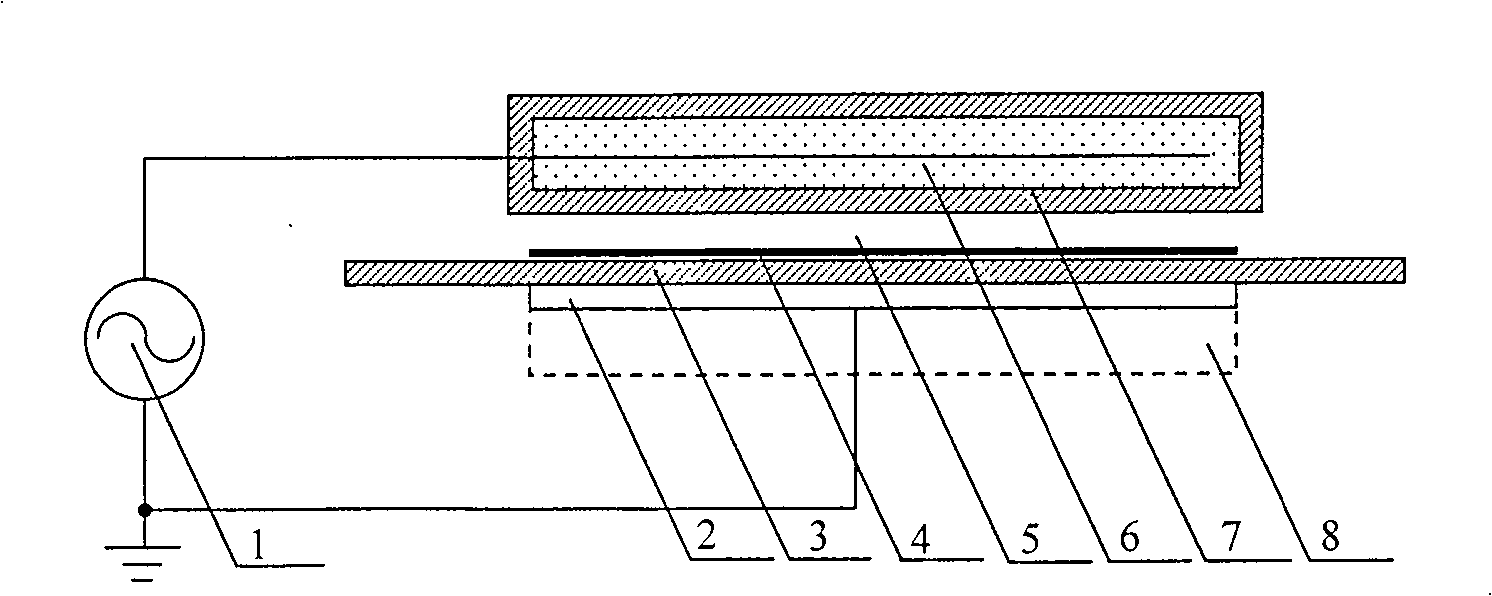
[0033] The structure of Embodiment 1 of the present invention is as follows figure 1 as shown, figure 2 Its side structure schematic diagram, figure 1 The direction of the middle arrow is the transmission direction of sample 4. The high-voltage electrode in this embodiment is a high-voltage electrode dielectric tube 7 sealed and filled with metal powder 6 inside the tube. The high-voltage end of the high-frequency power supply 1 is inserted into the high-voltage electrode dielectric tube 7 through a wire. The grounding electrode is a metal plate 2 covered with a dielectric plate 3, the dielectric plate 3 is in close contact with the metal plate 2, and the ground terminal of the high-frequency power supply 1 is connected to the metal plate 2 through a wire. During specific installation, the metal powder 6 is poured into the high-voltage electrode dielectric tube 7 with one end sealed, and the high-voltage end wire of the high-frequency power supply 1 is inserted into the met...
Embodiment 2
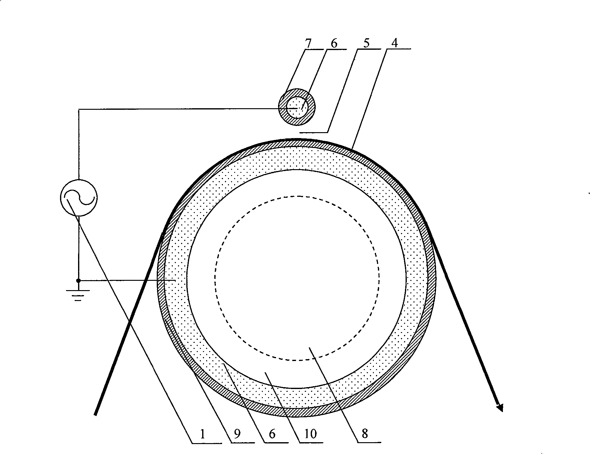
[0036] The structure of the second embodiment of the present invention is as image 3 As shown, the high-voltage electrode of this embodiment is a high-voltage electrode dielectric tube 7 sealed and filled with metal powder 6 , and the high-voltage end of the high-frequency power supply 1 is inserted into the high-voltage electrode dielectric tube 7 through a wire. The grounding electrode is a casing composed of an inner tube and an outer tube. The outer tube is a grounding electrode dielectric tube 9 whose curvature radius is greater than that of the high-voltage electrode dielectric tube 7. The curvature radius of the grounding electrode dielectric tube 9 is at least equal to that of the high-voltage electrode dielectric tube 7 times the radius of curvature. The inner tube is a metal tube 10, and the gap layer formed by the inner wall of the outer tube and the outer wall of the inner tube is sealed and filled with metal powder 6. The ground terminal of the high-frequency po...
Embodiment 3
[0039] The structure of the third embodiment of the present invention is as follows Figure 4 As shown, in this embodiment, a plurality of high-voltage electrode dielectric tubes 7 sealed and filled with metal powder 6 are used in this embodiment. There are four high-voltage electrode dielectric tubes 7 arranged side by side as high-voltage electrodes. The high-voltage end of the high-frequency power supply 1 is inserted into the high-voltage electrode dielectric tube 7 through a wire. The grounding electrode is a metal plate 2 covered with a dielectric plate 3. The dielectric plate 3 is in close contact with the metal plate 2. The ground terminal of the high-frequency power supply 1 is connected to the metal plate 2 through wires. During specific installation, the metal powder 6 is poured into the high-voltage electrode dielectric tube 7 with one end sealed, and the high-voltage end wire of the high-frequency power supply 1 is inserted into the metal powder 6 until one end of...
PUM
 Abstract
Description
Claims
Application Information
 - R&D
- Intellectual Property
- Life Sciences
- Materials
- Tech Scout
- Unparalleled Data Quality
- Higher Quality Content
- 60% Fewer Hallucinations
Browse by: Latest US Patents, China's latest patents, Technical Efficacy Thesaurus, Application Domain, Technology Topic, Popular Technical Reports.
© 2025 PatSnap. All rights reserved.Legal|Privacy policy|Modern Slavery Act Transparency Statement|Sitemap|About US| Contact US: help@patsnap.com


