Phase change heat storage heat supply device

A technology of phase-change heat storage and heat supply devices, which is applied in the field of heat supply devices and heat supply devices with phase-change heat storage devices, can solve the problem that solar energy storage heat cannot be well used and cannot play a very important role. Good heat storage and heat release effect, fast decay of heat storage and heat release process, etc., to achieve the effect of ensuring stability, improving heat absorption and release, and reducing equipment volume

Inactive Publication Date: 2009-10-07
皇明太阳能(上海)有限公司
View PDF5 Cites 0 Cited by
  • Summary
  • Abstract
  • Description
  • Claims
  • Application Information

AI Technical Summary

Problems solved by technology

The phase change heat storage body is dispersedly placed in the water or oil loaded in the water tank, the heat stored by the phase change material is transferred to the water or oil in the water tank through the phase change material shell, and then the water or oil in the water tank is heat exchanged The two heat transfers require a large enough heat transfer area and a large enough temperature difference. Since the phase change material is dispersed in the water tank, there are relatively few phase change cold storage bodies per unit volume. The heat storage and heat release process of the variable material decays quickly, and it cannot play a good heat storage and heat release effect. Therefore, the heat supply of the equipment during operation comes from the water or oil in the water tank, or from gas or electricity. Heating, the heat stored by the solar energy is not well used

Method used


Image

  • Phase change heat storage heat supply device
  • Phase change heat storage heat supply device

Examples


Embodiment 1

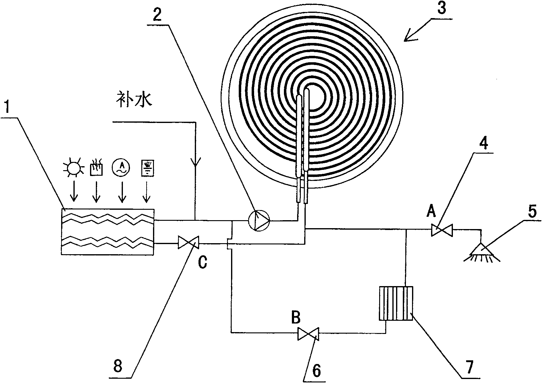
[0018] Embodiment 1: The first heat storage mode. When there is no heat consumption, the external energy heater 1 is heated by solar energy or industrial waste heat, or electric heating is performed by using cheap electricity at night, the thermal storage mode starts, and the working process is: A valve 4 and B valve 6 are closed, and the external energy heater 1 Heating by solar energy or industrial waste heat, or using cheap electricity at night for electric heating, the valve 8 is opened, and the heat is transferred from the external energy heater 1 to the three-dimensional double involute phase change heat accumulator 3 with the medium water under the action of the circulating water pump 2 , is accumulated, and the state of heat storage agent 17 changes from solid to liquid.

Embodiment 2

[0019] Implementation 2: The second phase change heating mode. When the three-dimensional double involute phase change heat accumulator 3 has sufficient heat storage and cannot obtain solar energy or waste heat heating, the C valve 8 is closed, and the external energy heater stops working. When the shower 5 is working, the A valve 4 is opened, and the external water supply is pressurized by the water circulation pump 2 and enters the three-dimensional double involute phase change heat accumulator 3 to obtain heat and heat up for the shower 5 or domestic water use. When the heat sink 7 is working, the B valve 6 is opened, and the heat is transferred from the three-dimensional double involute phase change heat accumulator 3 to the heat sink 7 with the medium water under the action of the circulating water pump 2 . The state of the heat storage agent changes from solid to liquid.

Embodiment 3

[0020] Implementation 3: The third hybrid heating mode. When the three-dimensional double involute phase change heat accumulator 3 has sufficient heat storage and cannot obtain solar energy or waste heat heating, the phase change heating mode starts, and the working process is: C valve 8 is closed, and the external energy heater 1 stops working. The A valve 4 is opened, the shower 5 works, and the external water supply is pressurized by the water circulation pump 2 and enters the three-dimensional double involute phase change heat accumulator 3 to obtain heat and heat up for the shower to use. The B valve 6 is opened, the heat sink 7 is working, and the heat is transferred from the three-dimensional double involute phase change heat accumulator 3 to the heat sink 7 with the medium water under the action of the circulating water pump 2 . The state of heat storage agent 17 changes from solid to liquid.

[0021] When both heat supply and solar or waste heat heating are required,...


PUM


Abstract

The phase change heat storing and supplying apparatus includes external energy source heater, water circulating pump, phase change heat storing device, valve A, valve B, valve C, heat sink, and shower connected together. By means of the direct phase change heat storing and releasing mode and stereo double involute heat accumulator, the present invention has homogeneous distribution of heat exchange pipe inside the heat accumulator, raised heat absorbing and releasing efficiency of the heat accumulating agent, reduce water flow pipe resistance and heat transfer temperature difference, increased heat accumulating capacity per unit volume, reduced apparatus size, full utilization of solar energy, waste heat and low price electric power, and stable hot water supply.

Description

technical field [0001] The invention relates to a heat supply device, in particular to a heat supply device with a phase change heat accumulator, which belongs to the technical field of energy utilization. Background technique [0002] At present, in my country and the world, the growth of electric power cannot meet the needs of rapid economic development and the rapid growth of domestic electricity consumption. The situation of power shortage in the country still exists, the load rate of the power grid is low, the difference between the peak and valley of the system is large, and the peak power is seriously insufficient. Valley difference accounts for up to 30% of the peak load. [0003] Electric heating for production or living occupies a large part of my country's energy consumption structure. In order to save production or living costs, the electric hot water supply system required for living or production adopts diversified energy sources. The shortcomings of traditional...

Claims


Application Information

Patent Timeline
Patent Type & Authority Patents(China)
IPC IPC(8): F28D20/00
CPCY02B10/20Y02E70/30Y02E60/142Y02E60/14
Inventor 苏树强曹宝文丁志华
Owner 皇明太阳能(上海)有限公司
Why Eureka
Try Eureka