
Piston ring and method for producing the same

A technology for piston rings and coatings, which is applied to piston rings, machines/engines, mechanical equipment, etc. It can solve the problems of not being able to reach the contact state near the seam, the life of the polishing sleeve is short, and it takes a long time to polish, so as to achieve film formation. The effect of short time, low cost, and improved yield

Inactive Publication Date: 2009-10-14
RIKEN CO LTD
View PDF4 Cites 0 Cited by
  • Summary
  • Abstract
  • Description
  • Claims
  • Application Information

AI Technical Summary

Problems solved by technology

It is easy to produce defects in the contact state of the outer peripheral part near the seam. Not only does it take a lot of polishing time to achieve the complete contact state of the outer peripheral surface, but in the worst case, even if the film in other parts becomes non-existent, the The contact state near the seam cannot be achieved
[0015] In addition, since the inner peripheral surface of the polishing sleeve is worn, the life of the polishing sleeve is extremely short, and thus, there is a disadvantage of high cost.

Method used


Image

  • Piston ring and method for producing the same
  • Piston ring and method for producing the same
  • Piston ring and method for producing the same

Examples


Embodiment Construction

[0035] Hereinafter, embodiments of the present invention will be described in detail.

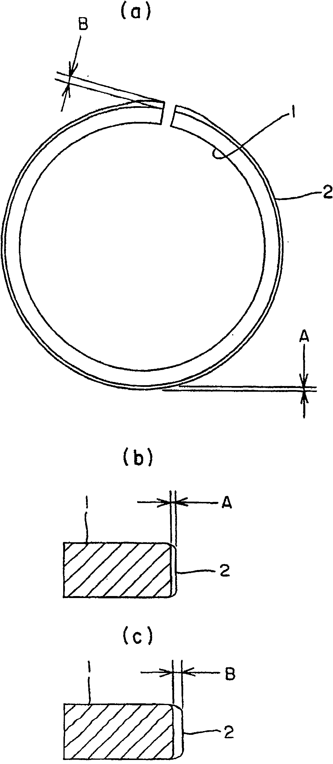
[0036] figure 1 , Is a piston ring showing an example of the present invention. In the figure, (a) is a plan view of the piston ring 1 as viewed from the axial direction, (b) is a radial cross-sectional view of the opposite part of the joint of the piston ring 1, and A represents the thickness of the piston ring coating 2. (c) is a cross-sectional view showing the vicinity of the joint in the radial direction, and B is the thickness of the piston ring coating 2. (c) shows a cross-sectional view in the radial direction near the joint, and B is the thickness of the piston ring coating 2.

[0037] Hereinafter, a representative manufacturing process of the above-mentioned piston ring will be described.

[0038] First, by winding any steel wire rods of various cross-sectional shapes, they are formed into the approximate shape of a piston ring. The shape of the outer peripheral surface at this time...


PUM

PropertyMeasurementUnit
thicknessaaaaaaaaaa
thicknessaaaaaaaaaa

Abstract

A low-cost piston ring manufacturing method is developed as a countermeasure against abrasion and breakage of the seam portion of the piston ring on which the coating is provided. The thickness of the coating (2) near the joint (7) of the piston ring (1) is thicker than the thickness of the coating (2) on the other outer peripheral surfaces. The raw material (5) of the piston ring rotates relative to the evaporation source (4), and when the seam (7) faces the evaporation source (4), the speed decreases.

Description

Technical field [0001] The present invention relates to a piston ring for an internal combustion engine, and more specifically, to a piston ring for an internal combustion engine having an improved coating and thickness on its outer peripheral surface, and a method of manufacturing the same. Background technique [0002] In recent years, with the increase in power of engines and measures to minimize the pollution of the atmosphere, the use environment of piston rings has become increasingly harsh, and the wear of the outer peripheral surface of the piston rings has become a problem. As a countermeasure, the existing hard chromium plating film and nitriding treatment are changed, and the outer peripheral surface is coated by ion plating with a hard film with excellent sintering resistance and abrasion resistance, such as chromium nitride and nitriding Piston rings with coatings such as titanium. [0003] However, in diesel engines that use such nitrides provided as a hard coating ...

Claims


Application Information

Patent Timeline
Patent Type & Authority Patents(China)
IPC IPC(8): F16J9/26F02F5/00C23C14/32C23C14/50C23C14/54F16J9/14
CPCC23C14/542C23C14/505F16J9/14F16J9/26F02F5/00
Inventor 三井田浩
Owner RIKEN CO LTD
Learn More