Optical component for optical communication

A technology of optical components and optical communication, applied in the direction of optical components, optics, light guides, etc., can solve the problems of discarding optical components, increasing the number of problems, deviation of optical characteristics, etc., achieve high-precision optical characteristics, improve degrees of freedom, and reduce size Effect

Inactive Publication Date: 2007-07-25
NIPPON ELECTRIC GLASS CO LTD
View PDF5 Cites 9 Cited by
  • Summary
  • Abstract
  • Description
  • Claims
  • Application Information

AI Technical Summary

Problems solved by technology

Therefore, due to the fact that each constituent element cannot be reduced in size, the amount of expansion or contraction of each constituent element significantly changes under the effect of temperature changes during use of the optical collimator, which causes optical characteristic deviation
In particular, when stress is concentrated on each of the lenses 4X, 4Y, and 4Z due to a difference in coefficient of thermal expansion, such a problem occurs that a deviation in optical characteristics including a refractive index and light dispersion occurs. An increase in the number of issues leading to a decrease in the stability of the optical system
According to this configuration, for example, in the case of an optical component for optical communication whose optical characteristics are significantly affected by the outgoing mode of light output from the end of the optical fiber and the incident mode of light incident on the end of the optical fiber, as in the case of the above-mentioned light The input and output modes of the light incident on and output from the end of the fiber cannot be adjusted at all, as represented by the collimator
Therefore, it is impossible to (finely) adjust the optical characteristics to have desired characteristics when the optical fiber and the lens are combined with each other or after the optical fiber and the lens are combined with each other, even if there is such a need
Therefore, a slight deviation or the like is caused in the optical characteristics, which causes a serious problem that an optical component for optical communication that cannot obtain the desired optical characteristics must be used without any adjustment, or such an optical component must be discarded as useless

Method used


Image

  • Optical component for optical communication
  • Optical component for optical communication
  • Optical component for optical communication

Examples


example 1

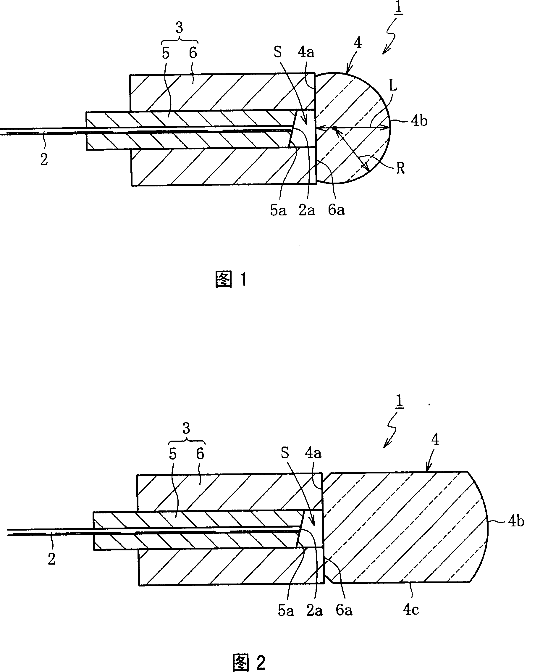
[0057] In Example 1 of the present invention, an optical collimator 1 having the structure shown in FIG. 1 (first embodiment) was manufactured. In the light collimator 1 according to Example 1, the first holding member 5 is made of glass, has an outer diameter of 0.25 mm, an inner diameter of 0.126 mm, and a total length of 3 mm. The end face of the first holding member 5 was ground so that the end face was inclined at an inclination angle of 8 degrees with respect to the normal to the optical axis, thereby forming an inclined surface 5 a. The optical fiber 2 is held in the inner hole of the first holding member 5, wherein the end face of the optical fiber 2 is ground together with the end face of the first holding member 5 (before the inclined surface 5a is formed). The second holding member 6 of the optical collimator 1 is made of glass, has an outer diameter of 1 mm, an inner diameter of 0.255 mm, and a total length of 2 mm. The second holding member 6 is fitted to the out...

example 2

[0063] In Example 2 of the present invention, an optical collimator 1 having the structure shown in FIG. 2 (second embodiment) was fabricated. In light collimator 1 according to Example 2, for example, in each of first holding member 5 and second holding member 6 , the size and material of each part are the same as in Example 1 described above. The lens 4 of the light collimator 1 is formed with a spherical lens as an initial lens, which has a diameter of 2 mm and is made of optical glass RH-21 (manufactured by Nippon Electric Glass Co., Ltd.) having a substantially uniform refractive index. . A part of the spherical lens is subjected to grinding processing or the like so that the distance between the end vertices of the flat surface portion 4 a and the spherical surface portion 4 b becomes 1.8 mm. The bonding state between the second holding member 6 and the lens 4 and the fact that the antireflection coating is formed in place are the same as in Example 1 above. In order t...

example 3

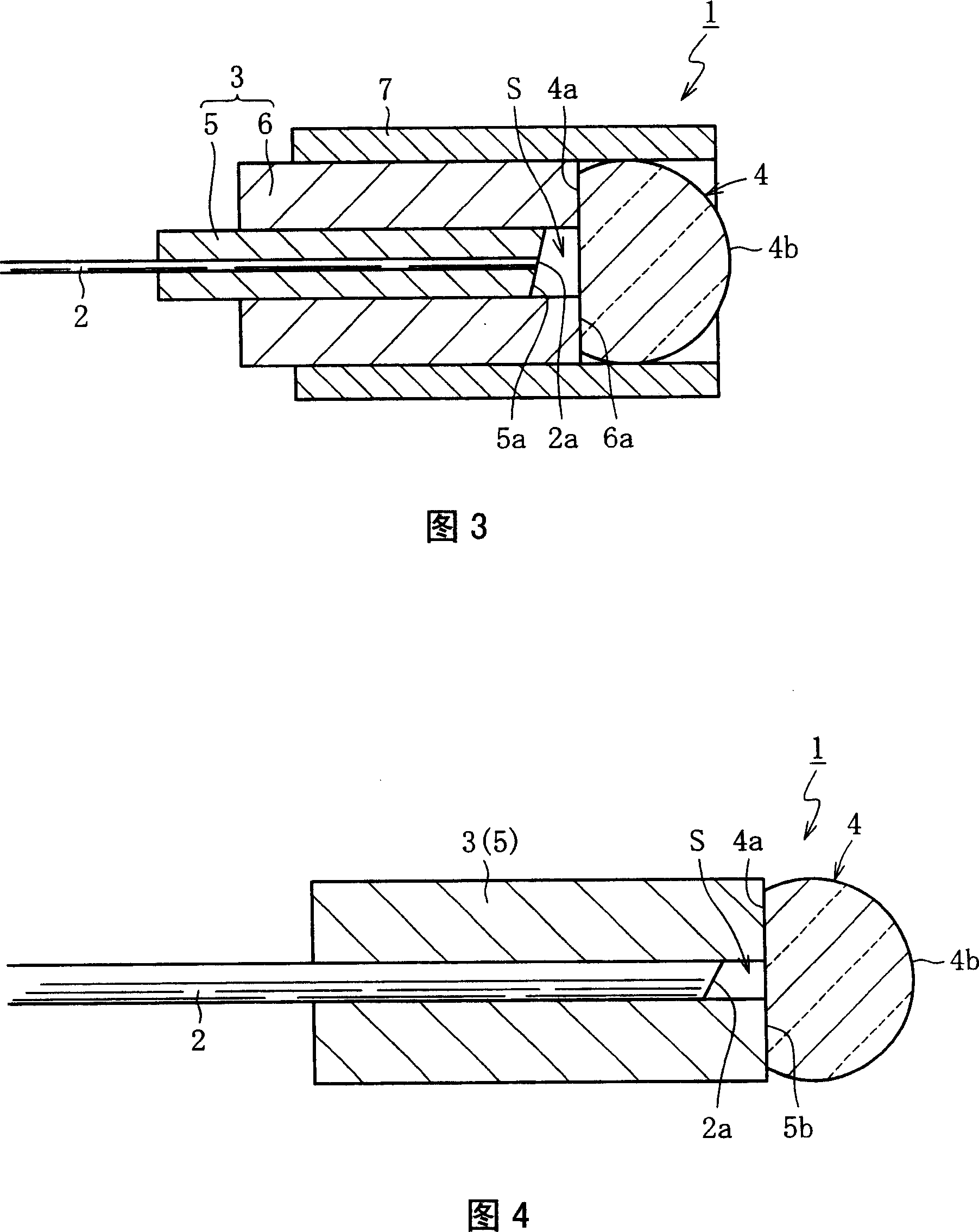
[0069] In Example 3 of the present invention, an optical collimator 1 having a structure as shown in FIG. 3 (third embodiment) was manufactured. In light collimator 1 according to Example 3, for example, in each of first holding member 5 and second holding member 6 , the size and material of each part are the same as those in Example 1 or 2 described above. The lens 4 of the light collimator 1 is formed with a spherical lens as an initial lens, which has a diameter of 1 mm and is made of optical glass RH-21 (manufactured by Nippon Electric Glass Co., Ltd.) having a substantially uniform refractive index. . A part of the spherical lens is subjected to grinding processing or the like so that the distance between the end vertices of the planar portion 4 a and the spherical portion 4 b becomes 0.7 mm. The outer sleeve 7 of the optical collimator 1 is made of glass, with an outer diameter of 1.4 mm, an inner diameter of 1 mm, and a total length of 3 mm. While the flat portion 6a ...


PUM

PropertyMeasurementUnit
diameteraaaaaaaaaa
lengthaaaaaaaaaa
diameteraaaaaaaaaa

Abstract

Provided is an optical component for optical communication which is capable of suitably accepting a request to reduce a size, resisting a thermal expansion coefficient difference between constituent elements, and adjusting incident and exit modes relative to an end of an optical fiber to thereby constantly attain optical characteristics which correspond to the request. The optical component includes a fiber holding member (3) holding an optical fiber (2), and a lens (4) which is located on an optical path extending from an end of the optical fiber (2) and attached to the fiber holding member (3). A flat portion (4a) formed in a rear end of the lens (4) is bonded to be fixed to a flat portion (6a) of an end of the fiber holding member (3) such that the flat portion (4a) of the lens (4) is opposed to the end of the optical fiber (2). A gap is provided between the flat portion (4a) of the lens (4) and the end (2a) of the optical fiber (2).

Description

technical field [0001] The present invention relates to an optical component for optical communication, and, more specifically, the present invention relates to a technique for properly fixing a lens to an optical fiber holding member for holding an optical fiber. Background technique [0002] In the field of optical communication, it is known that an optical module is frequently used, which includes, for example, a semiconductor light-emitting element like a laser diode, a semiconductor light-receiving element like a photodiode, and an optical fiber, and these elements interact with each other. Optically combined. A component widely used to construct this optical module or another optical module similar thereto is an optical component for optical communication, which includes: an optical fiber holding member for holding an optical fiber in an inner hole; and a lens, It is located on the optical path extending from the end of the optical fiber and is connected to the above-...

Claims


Application Information

Patent Timeline
Patent Type & Authority Applications(China)
IPC IPC(8): G02B6/32G02B3/00G02B1/00H04B10/02G02B1/11
CPCG02B6/327
Inventor 田中宏和和田正纪角见昌昭
Owner NIPPON ELECTRIC GLASS CO LTD
Why Eureka
Try Eureka