Direct injection pendulum type monopropellant engine

A pendulum engine and single component technology, which is applied in the direction of oscillating piston engines, rotating or oscillating piston engines, engine components, etc., can solve the problems that are difficult to meet the requirements of rapid power increase, the reduction of system energy density and power density, Reduce system energy and power density, etc., to achieve the effect of compact structure, reduced friction loss, and high energy conversion efficiency

Inactive Publication Date: 2007-08-01
SHENZHEN GRADUATE SCHOOL TSINGHUA UNIV
View PDF0 Cites 6 Cited by
  • Summary
  • Abstract
  • Description
  • Claims
  • Application Information

AI Technical Summary

Problems solved by technology

However, these energy supply devices or equipment have some shortcomings: the low energy density of chemical batteries makes it difficult to work for a long time; although fuel cells have higher energy density than chemical batteries, even if the problem of hydrogen storage technology is not considered , its low power density makes it unsuitable for applications that require a rapid increase in power; for the same output power, the electric actuator used with the above-mentioned chemical battery or fuel cell is generally larger than the hydraulic or pneumatic mechanism. Bulky, which leads to the reduction of system energy density and power density; for small internal combustion generator sets, although fossil fuels such as gasoline or diesel have high energy density, all hydrocarbon fuel engines except for their own moving parts such as crankshaft and piston In addition, complex auxiliary subsystems such as compression and ignition are also required; in addition, small internal combustion engines must operate at very high speeds to obtain good power density, so in order to match the internal combustion engine and actuator motion relationship, gear reduction devices are often essential This not only increases the complexity of the system but also reduces the energy and power density of the entire system; moreover, due to the dependence of hydrocarbon fuel internal combustion engines on oxygen in the air, they can be used in anaerobic or hypoxic environments (such as underwater or space) ) applications are very limited

Method used


Image

  • Direct injection pendulum type monopropellant engine
  • Direct injection pendulum type monopropellant engine
  • Direct injection pendulum type monopropellant engine

Examples


Embodiment Construction

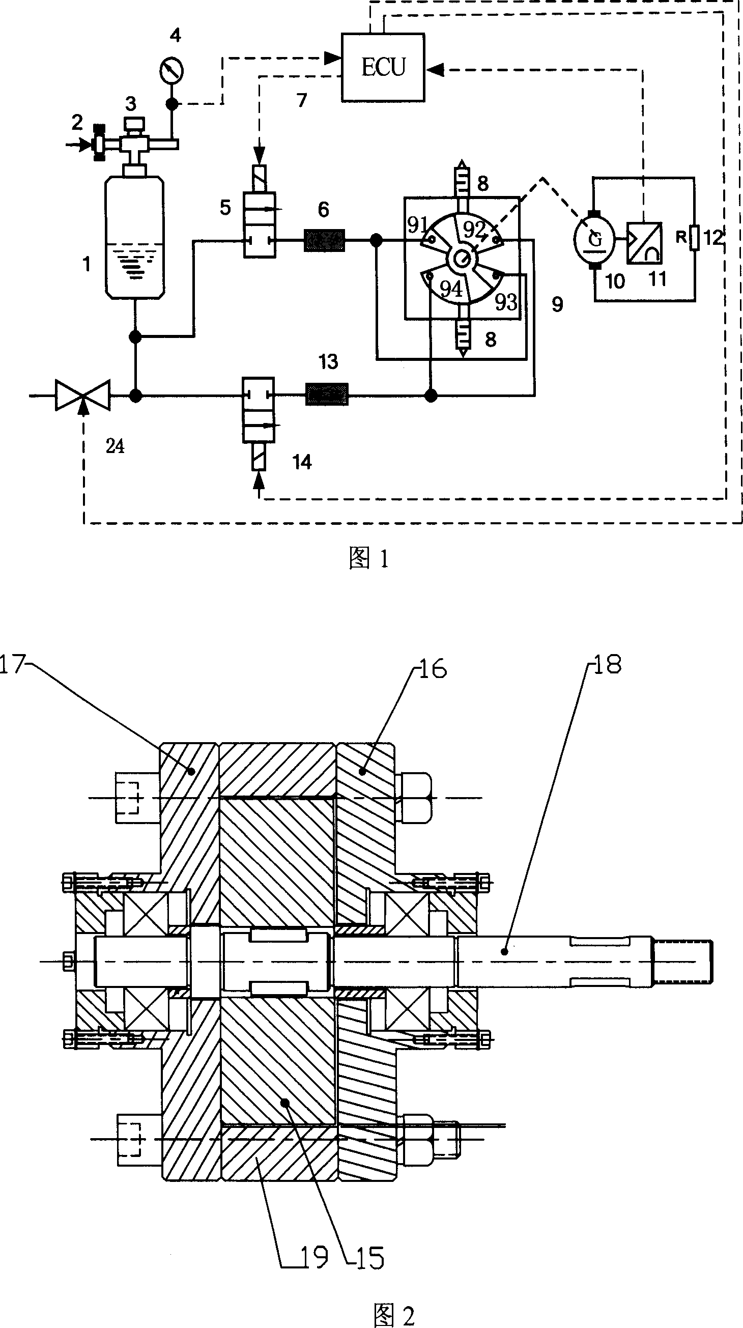
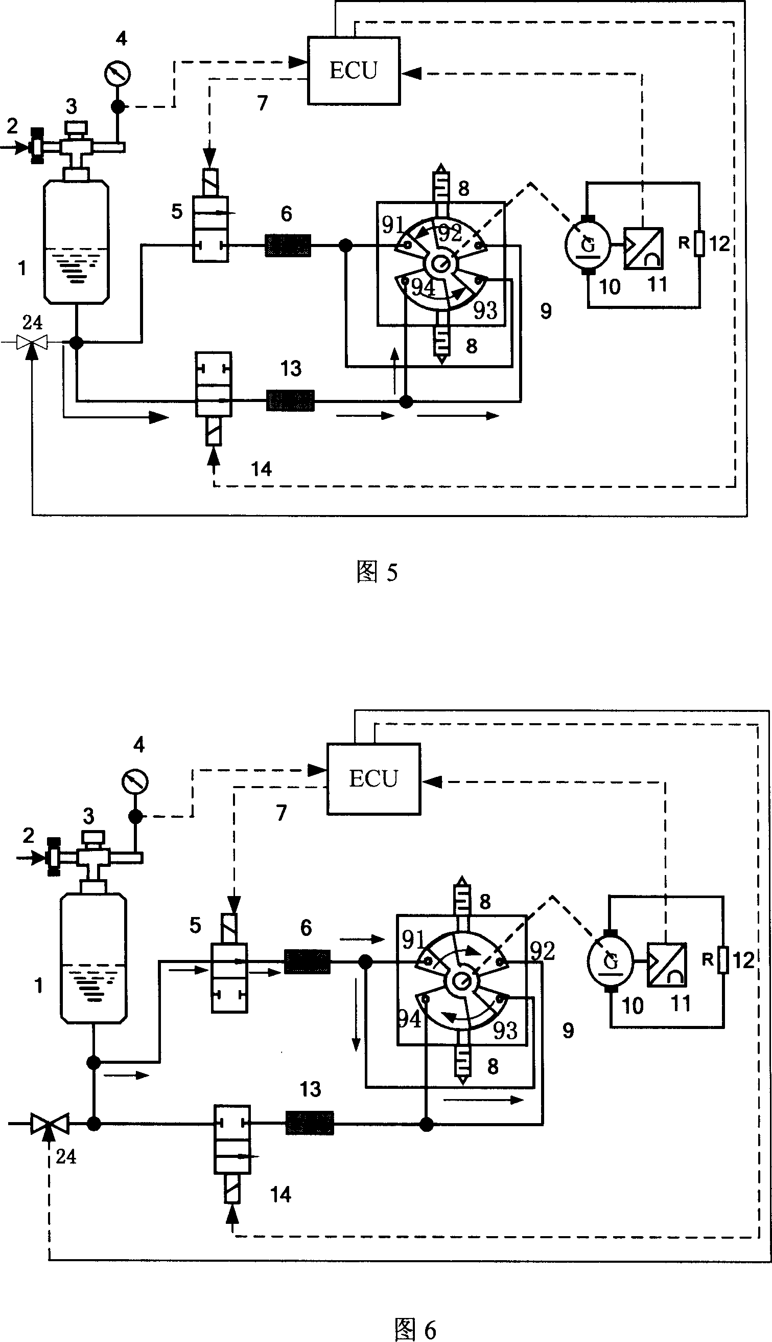
[0019] The direct-injection pendulum type mono-component engine of the present invention uses a mixture of high-concentration hydrogen peroxide and diesel oil as the mono-component fuel, and decomposes the above-mentioned mixed mono-component fuel into high-temperature and high-pressure mixed gas through catalytic decomposition to serve as a direct-drive pendulum type The working power of the engine realizes the direct output of the swing power or realizes the electric energy output through the generator. By controlling the on-off frequency of the two fuel control valves through the electronic control unit, the operating frequency of the engine swing or the frequency of the output alternating current can be controlled. This direct-injection pendulum single-component engine has the characteristics of small size, light weight, high energy density, few moving parts, reliable operation and wide application range. It is suitable for various anoxic or anoxic Energy supply devices wi...


PUM


Abstract

A direct-injection swing single-unit engine comprises a single-unit fuel pot, a swing engine, two fuel control electromagnetic valves, two catalysis beds and an electric controller. The invention uses the mixture of high-density hydrogen dioxide and diesel as the single-unit fuel, to be decomposed into high-temperature high-pressure mixture gas via catalysis decomposition, to drive the swing engine, to output swing power directly or output electricity via the generator. The electric controller can control two fuel control valves to switch the frequency to control the swing frequency of the engine or the frequency of output alternative-current. The invention has small volume, low weight, high energy density, and wide application, to be used to supply energy in non-oxygen condition or oxygen-lack condition.

Description

technical field [0001] The present invention relates to a single-component engine, in particular to energy supply devices such as miniature energy autonomous robots, portable electronic products, micro-electromechanical systems or equipment that can be used in the field, and anaerobic or anoxic environments (such as space, The direct or indirect utilization technology of swing power in underwater or plateau, etc., belongs to the field of energy and power technology. Background technique [0002] Most of the micro-energy autonomous robots, micro-electro-mechanical systems or equipment, and portable electronic products that operate in the field require a power level of 1mW to 1000W and an energy supply device with excellent performance. Generally speaking, the main energy supply devices in this power range are chemical batteries, fuel cells or small internal combustion generator sets. However, these energy supply devices or equipment have some shortcomings: the low energy den...

Claims


Application Information

Patent Timeline
Patent Type & Authority Applications(China)
IPC IPC(8): F01C9/00F01C13/00F01C20/00F01C21/00F01C21/10F01C21/18
Inventor 夏必忠汪劲松郁鼎文张辉刘学平段广洪毛乐山
Owner SHENZHEN GRADUATE SCHOOL TSINGHUA UNIV
Why Eureka
Try Eureka