
Manufacture method for double-humped resonance coating optical fiber grating gas-sensing sensor

A technology of coating fiber grating and gas sensor, which is applied in the measurement of phase influence characteristics, etc., to achieve high refractive index sensitivity, long-distance telemetry, and high cost performance.

Inactive Publication Date: 2007-08-15
UNIV OF SHANGHAI FOR SCI & TECH
View PDF0 Cites 5 Cited by
  • Summary
  • Abstract
  • Description
  • Claims
  • Application Information

AI Technical Summary

Problems solved by technology

Research in this area has not yet been reported

Method used


Image

  • Manufacture method for double-humped resonance coating optical fiber grating gas-sensing sensor

Examples


Embodiment Construction

[0031] The embodiments of the present invention will be described in further detail below in conjunction with the accompanying drawings, but the present embodiments are not intended to limit the present invention, and all similar methods and similar changes of the present invention should be included in the protection scope of the present invention.

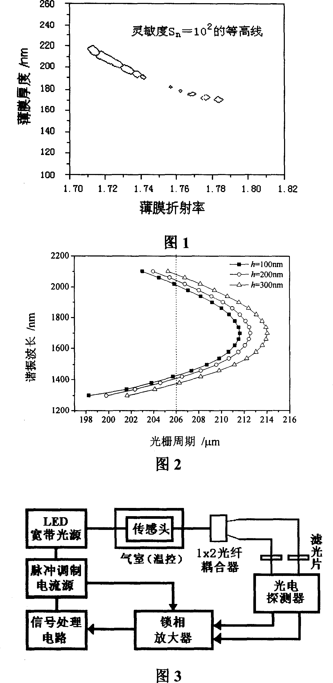
[0032] In order to maximize the variation of the distance between the double peaks of the transmission spectrum, it is necessary to select the appropriate optical parameters of the sensing film and the parameters of the grating to improve the sensitivity of the sensor. Therefore, there is a need for a new manufacturing method for long-period fiber grating thin film sensors. Compared with the traditional electrical block sensor, the optical thin film sensor has the characteristics of anti-electromagnetic interference, large dynamic range, high sensitivity and fast response; due to no electrical contact, it is especially suitable fo...


PUM

PropertyMeasurementUnit
lengthaaaaaaaaaa

Abstract

This invention relates to one double peak vibration coating fiber and grating sensor method in sensor process technique field, which comprises the following steps: a, selecting fiber grating; b, determining coat film thickness; c, determining double peak center wave length; d, fiber grating cover coating; e, sensor probe processing; f, double peak signal testing. This invention provides one small shaped, highly integrated and accurate film fiber and grating gas sensitive sensor process method.

Description

technical field [0001] The invention relates to the manufacturing technology of a gas sensor, in particular to a manufacturing technology of a bimodal resonant coated optical fiber grating gas sensor. Background technique [0002] Long-period fiber grating (long-period fiber grating, LPFG) is a light-induced fiber core refractive index change fiber device. Compared with Bragg fiber grating, LPFG is especially sensitive to the refractive index change of the medium around the cladding, and the resolution can reach 10 -5 , so it can be used as an ambient refractive index sensor. At present, it is mainly used in the measurement of solution concentration, especially in the monitoring and detection of petroleum industry, and its detection resolution can be compared with that of liquid chromatography and ultraviolet spectrometer. [0003] When the grating period is short (100 μm), for some cladding modes with higher orders, two resonance peaks will be observed during the grating ...

Claims


Application Information

Patent Timeline
Patent Type & Authority Applications(China)
IPC IPC(8): G01N21/41
Inventor 顾铮先
Owner UNIV OF SHANGHAI FOR SCI & TECH
Learn More