Aeration method, its apparatus and its system

An aeration device and aeration method technology, applied in water aeration, chemical instruments and methods, degassed water/sewage treatment, etc., can solve the problems of energy consumption, poor gas dissolution efficiency, and low efficiency, and achieve the promotion of convection , Prolong the aeration time, improve the effect of dissolution efficiency

Inactive Publication Date: 2007-08-15
池田 好明 +5
View PDF2 Cites 8 Cited by
  • Summary
  • Abstract
  • Description
  • Claims
  • Application Information

AI Technical Summary

Problems solved by technology

[0005] However, in the inventions disclosed in Patent Documents 1 and 2, the principle used is only to increase the contact area of ​​the air bubbles and the water body, and these two basic gas dissolution methods of increasing the contact time of the air bubbles and the water body. Therefore, the gas The efficiency of dissolution is very poor, and the water body that has been aerated and the water body that has not been aerated cannot be separated. In the above two methods, there is a process of secondary aeration of the water body that has been aerated, resulting in Unnecessary energy consumption, not very efficient

Method used


Image

  • Aeration method, its apparatus and its system
  • Aeration method, its apparatus and its system
  • Aeration method, its apparatus and its system

Examples


Embodiment Construction

[0186] Hereinafter, embodiments of the aeration method, aeration device, and aeration system of the present invention will be described based on FIGS. 1 to 15 .

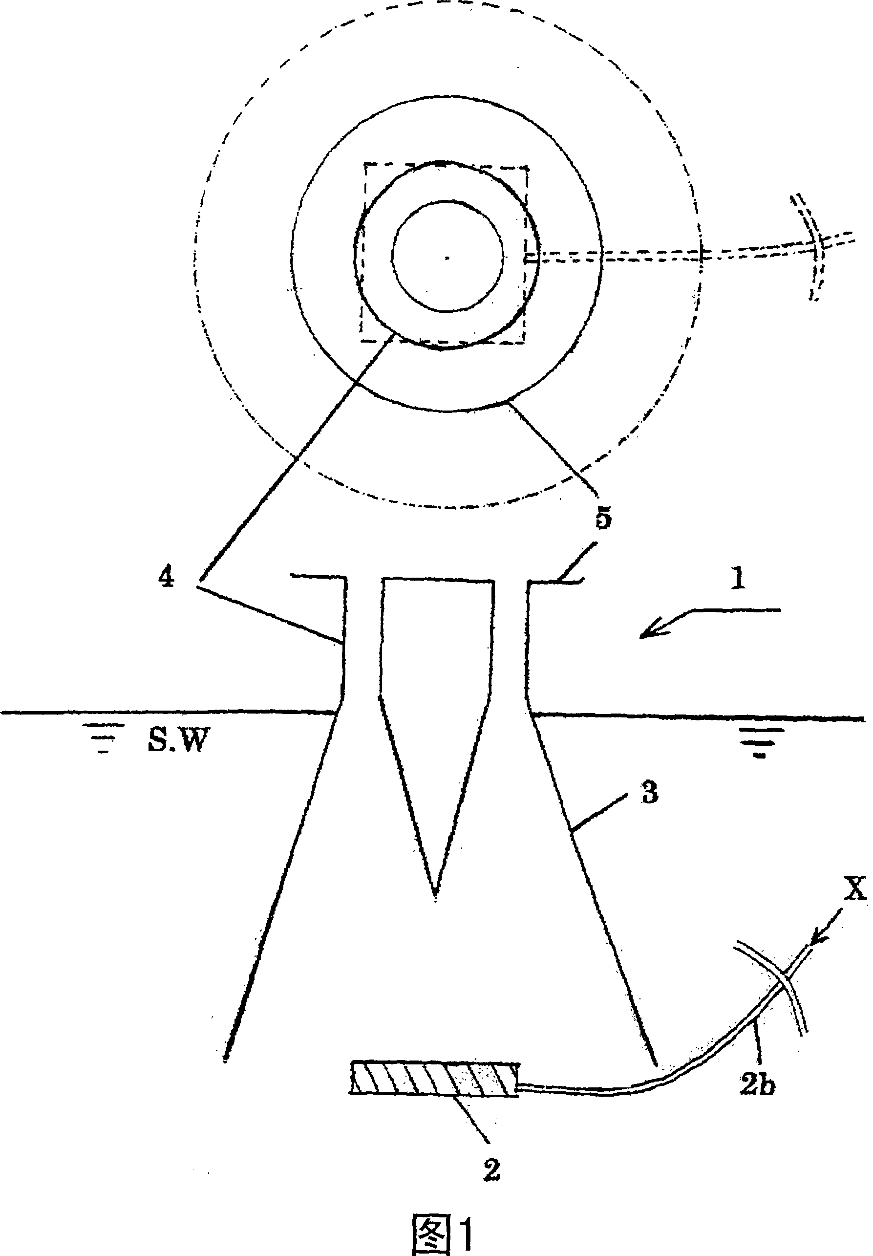
[0187] Fig. 1 is a conceptual diagram of an aerator according to a first embodiment, the upper side is a perspective view, and the lower side is a front view.

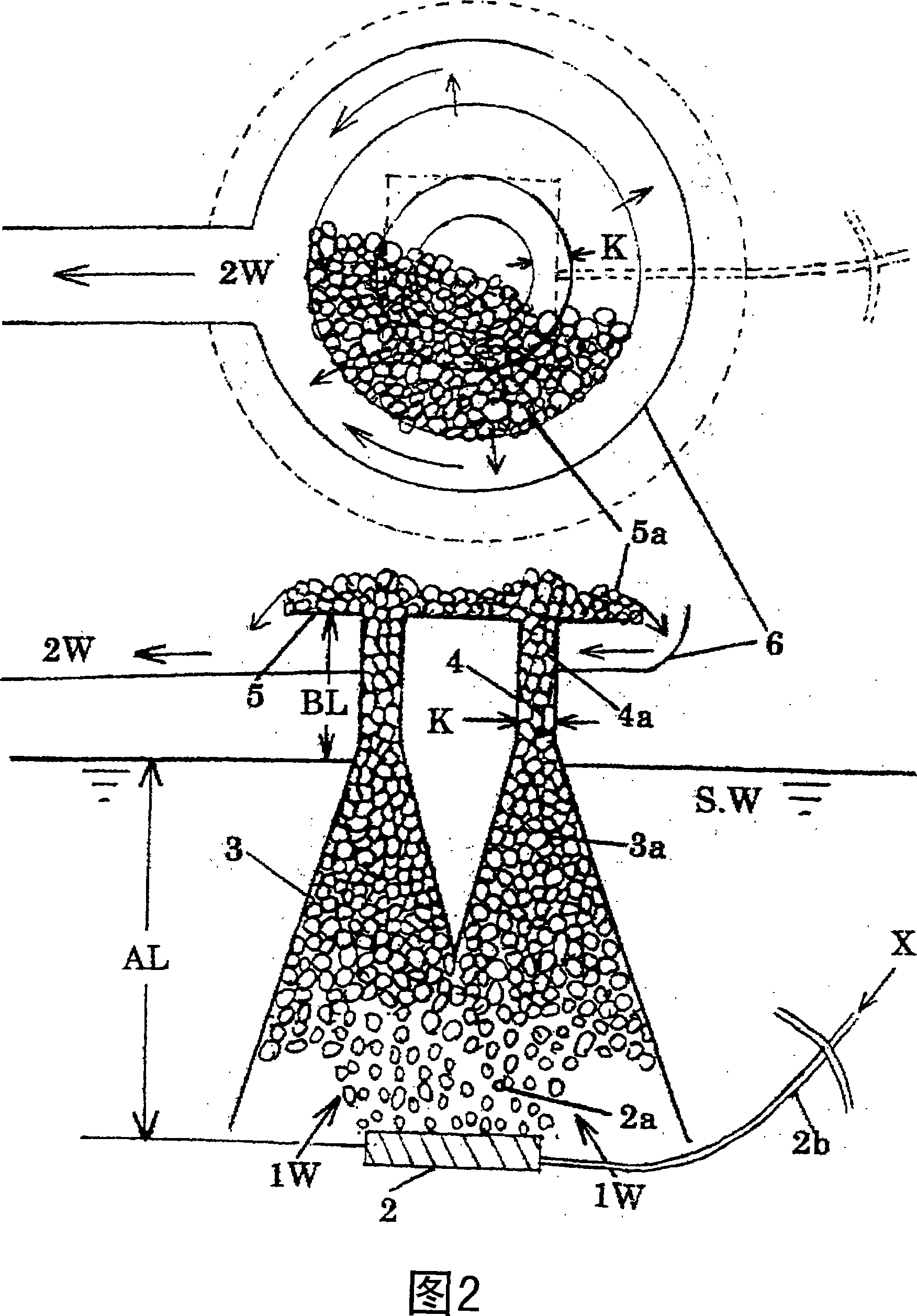
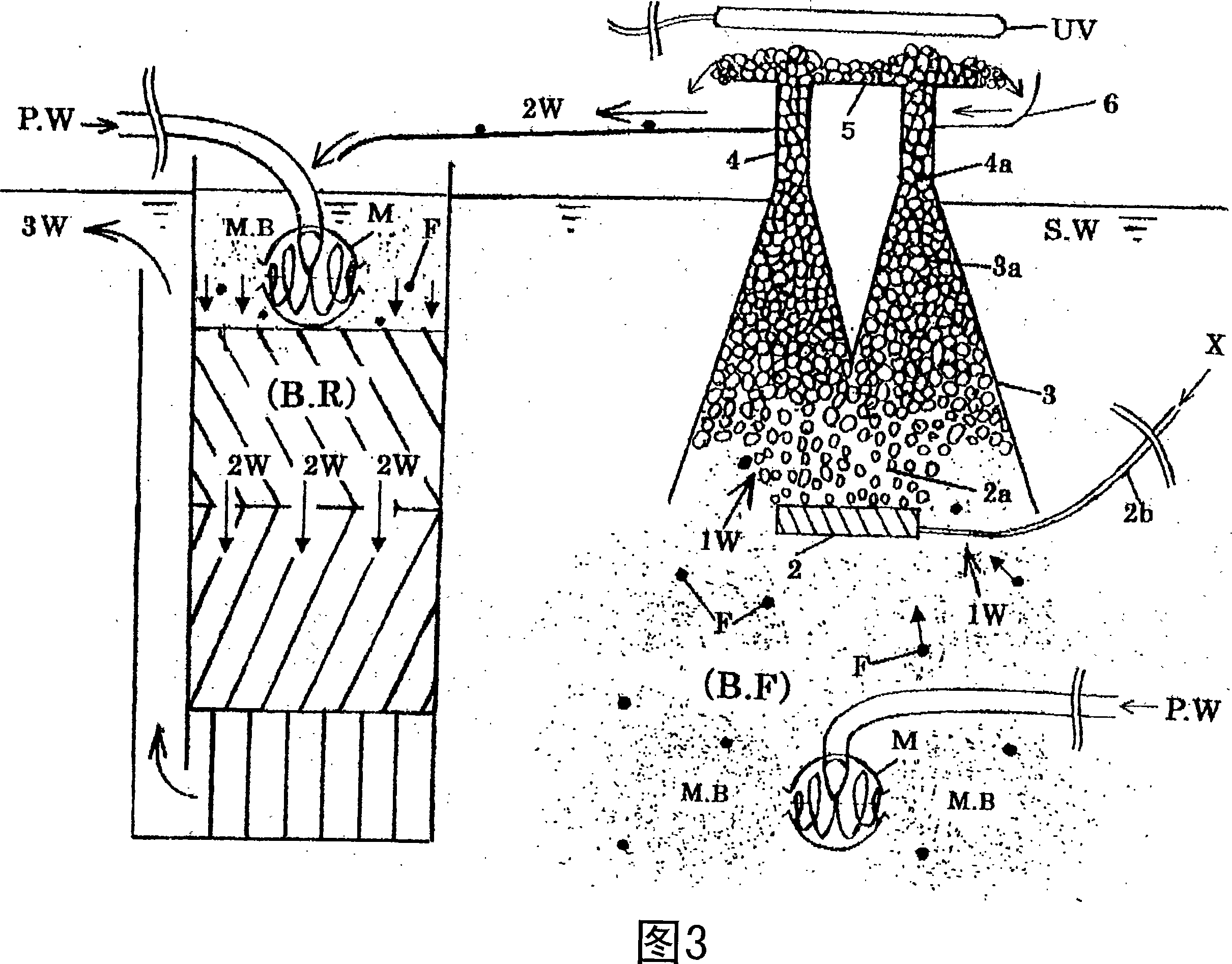
[0188] In Fig. 1, 1 is the aeration device according to the first embodiment, 2 is the air bubble generating part, 2b is a gas supply pipe for supplying gas to the air bubble generating part 2, and 3 is used to release the air bubbles generated from the air bubble generating part 2. The bubble concentration part that gathers together, 4 is the bubble ascending channel that can make the bubbles after the concentration rise to the position above the water surface S.W, 5 is the liquid bubble exposure that is used for prolonging the aeration time of the liquid bubbles produced in the bubble ascending channel 4 as much as possible in the atmosphere. Gas section, X...


PUM


Abstract

Provided are an aeration method, an aeration apparatus and an aeration system which allow, in a sewage disposal plant, a nursery for fish and shellfish and a closed water area in an ocean or the like, the highly efficient dissolution of an gas into the water to be treated and the transfer of the resultant treated water to another place by a water head difference by the use of a conventional apparatus for supplying a gas. An aeration apparatus, which comprises an gas spraying section (22) for generating gas bubble particles in the water to be treated (1W), a bubble rise section (3P) for allowing a mass of the gas bubble particles generated above to move upwards, a passage section (4P) for the rise of gas bubble particles, wherein the above gas bubble particles are pushed up to a position above a water surface and are changed into liquid bubbles, to thereby convert the water to be treated (1W) to a liquid film, and a liquid bubble transfer section (5P) wherein the treated water (2W) can be transferred by a water head difference.

Description

technical field [0001] The present invention relates to an aeration method, an aeration device and an aeration system for efficiently contacting liquids stored in sewage treatment plants or reservoirs with gases such as air and pure oxygen, and further relates to the following aeration devices and aeration systems, That is, by using the pressurized gas generated by an air pump or blower, the water stored in lakes, fish farms, animal and plant cell culture tanks, sewage treatment tanks, etc. is temporarily formed into vacuole groups (foamy clusters), thereby The water storage is formed as the surface liquid film of the bubble, so that the gas (oxygen or air, etc.) in the bubble can be efficiently contacted with the water body (surface liquid film), so that in the case of using air, not only the water body can be enriched The role of oxygen can also achieve the dissolved balance of oxygen and nitrogen, and obtain water suitable for biological survival. Background technique ...

Claims


Application Information

Patent Timeline
Patent Type & Authority Applications(China)
IPC IPC(8): C02F3/20A01K63/04C02F1/20C02F1/74C02F7/00
CPCC02F1/74A01K63/042C02F1/20C02F3/20C02F7/00Y02W10/10Y02W10/37
Inventor 藤里哲彦
Owner 池田 好明
Why Eureka
Try Eureka