Supercharge Your Innovation With Domain-Expert AI Agents!

Magnetic storage device

A magnetic storage and magnetic head technology, applied in information storage, recording information storage, magnetic recording, etc., can solve the problems of increased coercivity, difficulty in recording, and increased magnetic anisotropy of magnetic particles

Inactive Publication Date: 2007-10-03
HITACHI GLOBAL STORAGE TECH NETHERLANDS BV
View PDF4 Cites 4 Cited by
  • Summary
  • Abstract
  • Description
  • Claims
  • Application Information

AI Technical Summary

Problems solved by technology

However, in order to satisfy read and write performance and thermal stability, it is necessary not only to magnetically isolate the magnetic grains but also to increase the magnetic anisotropy of the magnetic grains, then there is a problem that the coercive force increases too much and recording by the magnetic head becomes difficulty

Method used


Image

  • Magnetic storage device
  • Magnetic storage device
  • Magnetic storage device

Examples


Embodiment 1

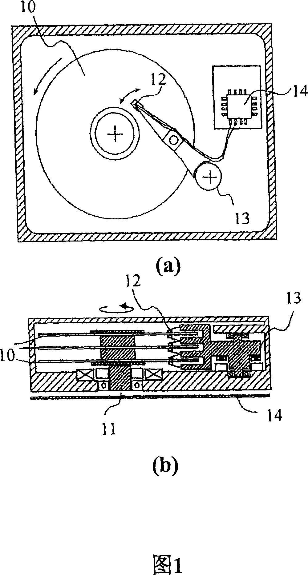
[0080] FIG. 1 is a schematic diagram showing one embodiment of a magnetic memory device according to the present invention.

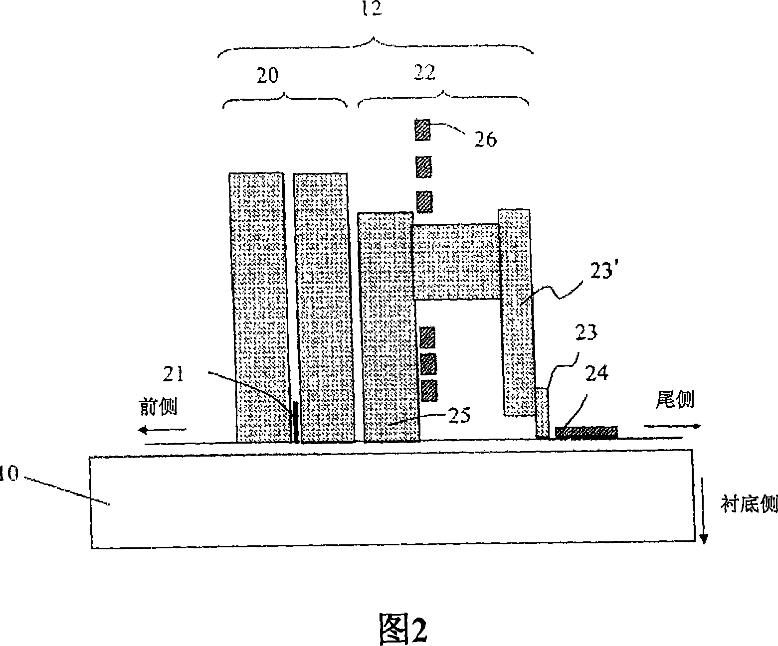
[0081] The magnetic storage device has a perpendicular magnetic recording medium 10, an actuator 11 for driving the perpendicular magnetic recording medium, a magnetic head 12 including a writer and a reader, a device 13 for moving the magnetic head relative to the magnetic recording medium, and a device for processing the given magnetic recording medium. Means 14 for input signals to the head and output signals from the head. FIG. 2 shows the relationship between the magnetic head 12 and the perpendicular magnetic recording medium 10 . The magnetic flying height of the magnetic head is 8nm. The reader 20 has a read element 21 sandwiched by a pair of magnetic shields, for which a giant magnetoresistive element (GMR) is used. In addition to the giant magnetoresistance element, the read element 21 may be a tunneling magnetoresistance element (TMR) or a ...

Embodiment 2

[0140] The magnetic storage device of this embodiment has the same structure as that of Embodiment 1 except for the perpendicular magnetic recording medium 10 . The perpendicular magnetic recording medium 10 was manufactured using the same sputtering system, layer structure, and process conditions as in Embodiment 1 described above. For the adhesive layer 42, Al-50 at.% Ti with a film thickness of 5 nm was used instead of the NiTa alloy. For the soft magnetic lower layer 43, 51at.%Fe-34at.%Co-10at.%Ta-5at.%Zr was used instead of the CoTaZr alloy. The film thickness of Ru in the AFC structure is 0.45 nm. In the fabrication medium, a value of 5 nm, 10 nm, 15 nm, 20 nm, 25 nm, 30 nm, 40 nm, or 50 nm was used for the film thickness of the FeCoTaZr alloy of each layer. A sample with a soft magnetic lower layer and no upper layer was also produced, and when a maximum magnetic field of 1035 kA / m was applied to the in-plane direction of the film using a vibrating sample magnetometer...

Embodiment 3

[0179] The magnetic storage device of this embodiment has the same structure as that of Embodiment 1 except for the perpendicular magnetic recording medium 10 . The perpendicular magnetic recording medium 10 was manufactured using the same sputtering system, layer structure, and process conditions as those in the aforementioned embodiment 1. For the adhesive layer 42, Al-50 at.% Ti of 5 nm film thickness was used instead of the NiTa alloy. For the soft magnetic lower layer 43, Fe-30at.%Co-15at.%B was used instead of the CoTaZr alloy. The film thickness of Ru in the AFC structure is 0.6 nm. In the fabrication medium, a value of 5 nm, 10 nm, 15 nm, 20 nm, 25 nm, 30 nm, 40 nm, or 50 nm is used for the film thickness of the FeCoB alloy of each layer. A sample with a soft magnetic lower layer and no upper layer was also fabricated, and when a maximum magnetic field of 1035 kA / m was applied to the in-plane direction of the film using a vibrating sample magnetometer, the estimated ...


PUM

PropertyMeasurementUnit
thicknessaaaaaaaaaa
saturation flux densityaaaaaaaaaa
thicknessaaaaaaaaaa

Abstract

A perpendicular magnetic recording medium and a shielded pole head are used. The shielded pole head comprises a single pole type writer having a main pole and an auxiliary pole, and a magnetic shield is provided via a non-magnetic gap layer so as to cover at least the down-track direction of trailing side of the main pole. The perpendicular magnetic recording medium has two recording layers. The first recording layer comprises ferromagnetic crystal grains having Co as principal component and containing at least Cr and Pt, and grain boundaries containing an oxide. The second recording layer comprises an alloy having Co as principal component, containing at least Cr, and not containing an oxide. The saturation magnetization Ms1 (kA / m) of the first recording layer, the saturation magnetization Ms2 (kA / m) of the second recording layer and the film thickness ts (nm) of the soft-magnetic underlayer satisfy the following relation: 20 + 0.033 * ts 2 + 2.3 * ts 4 / 3 * Ms 1 - Ms 2 329 - 0.024 - ts 2 + 1.9 * ts.

Description

technical field [0001] The present invention relates to a magnetic storage device capable of recording large amounts of information. Background technique [0002] In recent years, the amount of information handled by computers has increased, and the capacity of hard disk units as auxiliary recording means has also been required to further increase. In addition, due to the increased installation of hard disk drive units in household electronic products, there are more and more demands to reduce the size of the hard disk unit and increase the capacity of the hard disk unit. [0003] In the longitudinal magnetic recording system used in current magnetic disk units, the magnetizations recorded on the medium are opposite and adjacent to each other to increase the linear recording density, the coercive force of the recording layer must be increased and the film thickness must be decreased. However, if the coercive force of the recording layer is increased, there arises a problem ...

Claims


Application Information

Patent Timeline
Patent Type & Authority Applications(China)
IPC IPC(8): G11B5/738
CPCG11B5/66G11B5/11G11B5/1278G11B5/3146G11B5/315G11B5/656G11B2005/0029G11B5/674G11B5/672
Inventor 中川宏之武隈育子
Owner HITACHI GLOBAL STORAGE TECH NETHERLANDS BV
Features
  • R&D
  • Intellectual Property
  • Life Sciences
  • Materials
  • Tech Scout
  • Unparalleled Data Quality
  • Higher Quality Content
  • 60% Fewer Hallucinations
Learn More