Coal gasification device for circulating fluidized bed and manufacturing method thereof

A circulating fluidized bed and coal gasification technology, applied in the direction of granular/powdered fuel gasification, energy input, etc., to achieve the effect of facilitating daily maintenance, improving gasification efficiency, and reducing the carbon content of fly ash

Inactive Publication Date: 2007-10-17
宋建元
View PDF1 Cites 35 Cited by
  • Summary
  • Abstract
  • Description
  • Claims
  • Application Information

AI Technical Summary

Problems solved by technology

[0008] The technical solution given by the present invention is: this circulating fluidized bed coal gasification device includes a coal feeding system composed of coal crushing, screening equipment, coal storage tank and feeding bin, generator, cyclone dust collector, waste heat boiler , a water cooling tower and a Venturi scrubber, wherein the bottom of the feeding bin is provided with a spiral coal feeder for feeding coal to the producer, the producer is provided with upper and lower gasification agent nozzles, and the bottom of the producer is provided with a spiral Ash removal machine and ash storage tank, the upper part of the generator is provided with a gas pipe connected to the upper end of the cyclone dust collector, the bottom of the cyclone dust collector is provided with a return pipe connected with the generator furnace, and the cyclone dust collector is connected with the waste heat boiler through the gas pipe, and the waste heat The boiler communicates with the water-cooling tower through the gas pipe, and the water-cooling tower communicates with the Venturi scrubber through the gas pipe. It is characterized in that the return pipe from the lower end of the cyclone dust collector to the generating furnace is a feeder with a small fluidized bed. The amount of returned material can be dynamically adjusted, effectively realizing two key functions: one is to make the recirculated bed material return to the furnace continuously and stably from the cyclone dust collector; the other is to provide a gap between the negative pressure of the cyclone dust collector and the positive pressure of the lower combustion chamber The seal of the feeder is composed of a standpipe, a wind cap or an air duct, a bottom air chamber, a side air chamber, a return pipe, a fluidization chamber, a horizontal air distribution plate and a longitudinal air distribution plate, and the feeder is equipped with There are horizontal air distribution boards and vertical air distribution boards, and the space in the feeder is divided into three parts: the fluidization chamber, the bottom air chamber and the side air chamber. One end of the standpipe is connected with the cyclone dust collector. The other end is connected to the fluidization chamber, one end of the return pipe is connected to the fluidization chamber, and the other end is connected to the generator. The high-pressure gas from the blower enters the bottom air chamber and the side air chamber through the air inlet pipe. The backflow dust in the fluidization chamber is blown by the wind cap or air pipe on the air distribution board to form a small fluidized bed. A negative pressure zone is formed in the area below the joint, which not only facilitates the fly ash from the cyclone dust collector to enter the fluidization chamber smoothly through the standpipe, but also solves the problem of U-shaped, J-shaped, L-shaped return feeders in the prior art. The problem that the standpipe reverses and the amount of fly ash cannot be circulated back to the furnace through the return pipe when the amount of fly ash is small

Method used


Image

  • Coal gasification device for circulating fluidized bed and manufacturing method thereof
  • Coal gasification device for circulating fluidized bed and manufacturing method thereof

Examples


Embodiment Construction

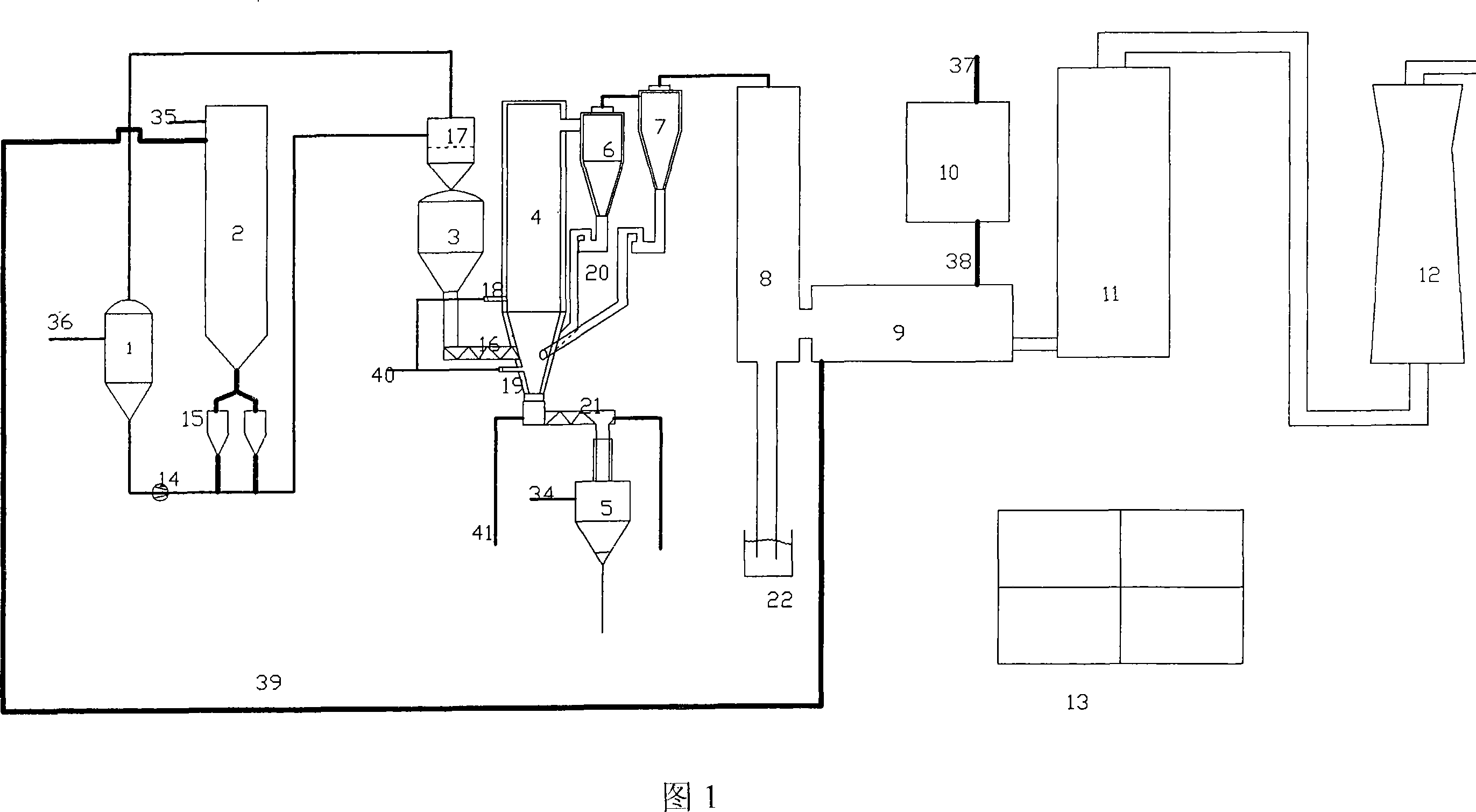
[0027] The concrete technical scheme of the present invention will be further described below in conjunction with embodiment:

[0028] As shown in Figure 1, this circulating fluidized bed coal gasification device includes a coal loading system composed of coal crushing and screening equipment 10, coal storage tank 2 and feeding bin 3, and is equipped with upper and lower gasification agents. The generator 4 of the nozzles 18 and 19, the cyclone dust collector composed of two sets of cyclone dust collectors 6 and 7 connected in series, the waste heat boiler 8, the water cooling tower 11 and the Venturi scrubber 12, wherein the bottom of the feeding bin 3 is provided with The spiral coal stoker 16 that sends coal to the generator 4, the bottom of the generator 4 is provided with a spiral ash remover 21 and the ash storage tank 5, and the upper part of the generator 4 is provided with a gas pipe communicating with the upper end of the previous group of cyclone dust collectors 6, ...


PUM


Abstract

A circulating fluidized bed coal gasification apparatus includes coal blending system, generator, cyclone dust collector, exhaust-heat boiler, water-cooling tower and Venturi scrubber, wherein the generator has up-and-down two rows of gasifying agent nozzles, helix dust collector and storage groove. The gas pipe which communicates to the cyclone dust collector is set on the top. A feed back pipe which communicates to the generator is set at the bottom of the cyclone dust collector. The cyclone dust collector communicates to the exhaust-heat boiler by gas pipe. The exhaust-heat boiler communicates to the water-cooling tower by gas pipe and communicates to the Venturi scrubber by gas pipe. The characteristics are: the feed back pipe facing to the generator hearth of the cyclone dust collector is a feed back machine with small-sized fluid bed; the cyclone dust collector is composed of at least two tandem dust collector; coal blending system has wind feeding and dust coal drier. The invention achieves the transition of the boiling bed to the circulating fluidized bed and increases the system gasification efficiency.

Description

technical field [0001] The present invention relates to a coal gas production equipment and its technological process, in particular to a circulating fluidized bed coal gasification device for coal gasification, especially low-quality coal gasification, and its preparation method. Process improvement belongs to coal gasification production technology. Background technique [0002] Coal gasification technology is mainly divided into three categories depending on the gas-solid state and movement form in the furnace: fixed bed with lump coal (10-50mm) as raw material; fluidized bed with pulverized coal (less than 10mm) as raw material; Pulverized coal (less than 0.1mm) is an entrained flow bed as raw material. In order to improve the capacity of a single furnace and reduce energy consumption, modern gasifiers are operated under an appropriate pressure (1.5-4.5MPa), and pressurized fixed bed, pressurized fluidized bed and pressurized entrained entrained bed technologies have ap...

Claims


Application Information

Patent Timeline
Patent Type & Authority Applications(China)
IPC IPC(8): C10J3/56
CPCY02P20/129
Inventor 宋建元
Owner 宋建元
Why Eureka
Try Eureka