Metallising using thin seed layer deposited using plasma-assisted process

A plasma and metallization technology, applied in the field of metallized plastic mesh and metallized plastic foil, can solve the problems of self-healing effect and disadvantage

Inactive Publication Date: 2007-11-07
APPLIED MATERIALS INC
View PDF1 Cites 3 Cited by
  • Summary
  • Abstract
  • Description
  • Claims
  • Application Information

AI Technical Summary

Problems solved by technology

[0006] However, for the self-healing properties of the zinc layer in foil capacitors, the above methods are disadvantageous because such a thick seed layer or nucleation layer would negatively affect this self-healing property

Method used


Image

  • Metallising using thin seed layer deposited using plasma-assisted process

Examples


Embodiment Construction

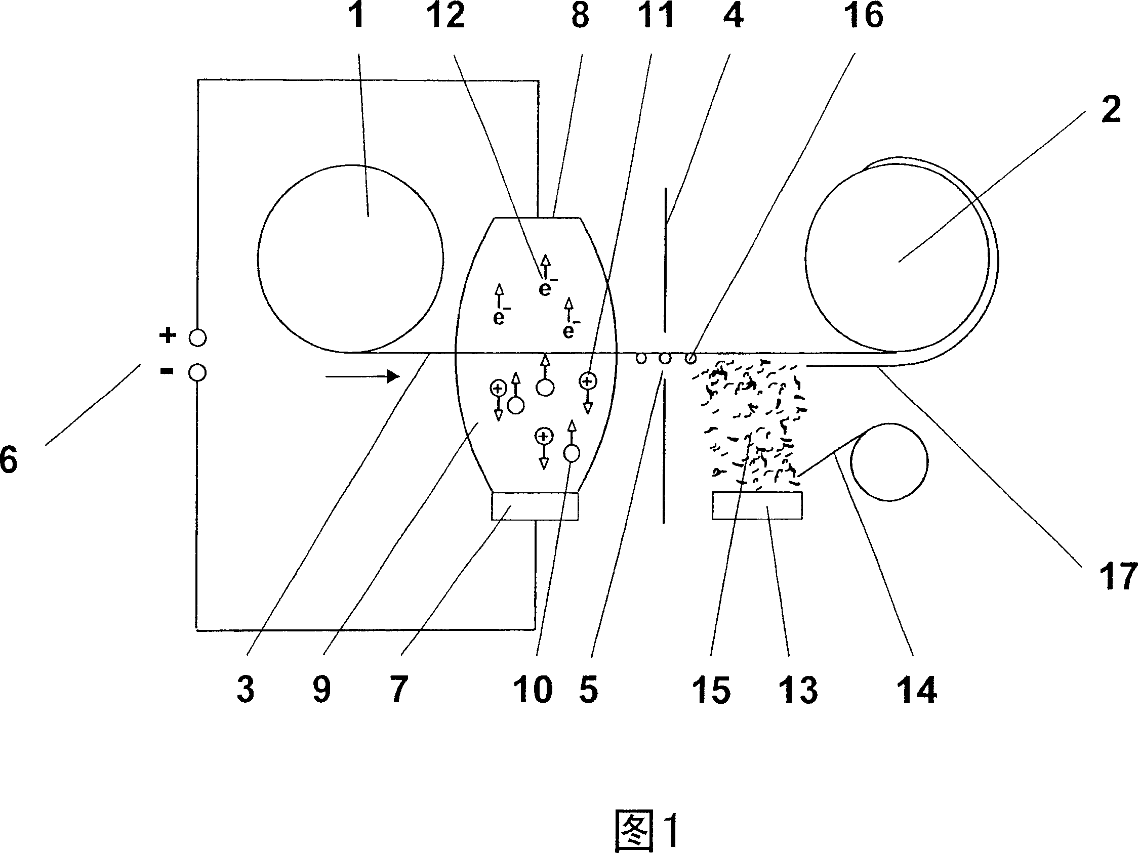
[0028] FIG. 1 represents a purely schematic illustration, in which only arranged components have been chosen to emphasize the basic principle, but these arranged components can deviate significantly under practical conditions.

[0029] The deposition machine has two rolls 1 and 2 . The plastic material (on which the deposition takes place) is set as foil 3 and this plastic foil is released from the first roll 1 according to the arrows shown next to roll 1 and moves towards roll 2, in roll 2 , the foil 3 is rolled up again accordingly.

[0030] Between the two rollers 1 and 2, two deposition or treatment stations are provided, which are preferably separated from each other by a chamber wall 4 in which an upper groove 5 or door assembly is provided, the foil The net 3 can be passed through the slot or door assembly described above.

[0031] The first deposition or processing station has a cathode 7 , an anode 8 and a DC power source or voltage source 6 , the negative terminal ...


PUM


Abstract

The invention relates to a making method for metalization meshwork (3) and equipment thereof, specifically relates to metalization plastic meshwork of foil capacitor. In said method, metallic layer (17) is deposited in vapor phase or gas-phase, wherein before the metallic layer is deposited, vapor phase or gas-phase deposition processes of metallic inoculating seed layer assisted by plasma, and the thickness of the metallic inoculating seed layer is in a scope of at most several atomic layers. Further, the invention also relates to plastic foil made by the said method, wherein the thickness of the inoculating seed layer between the metallic layer and plastic foil is that of at most several atomic layers.

Description

technical field [0001] The present invention relates to a method and an apparatus for producing a metallized mesh, in particular a metallized plastic mesh of a foil capacitor, in which the metal layer is deposited in the vapor phase or the gas phase, and a Metallized plastic foil. Background technique [0002] Metallized plastic foils can be used in various technical fields of application, for example, as foils for capacitors. The above-mentioned capacitor foil is composed of a non-conductive plastic foil such as polyester or polypropylene, and on the above-mentioned non-conductive plastic foil, a zinc metal layer is deposited to form an electrode. The above-mentioned process is usually carried out, for example, on a web deposition machine, in which the plastic material (on which the deposition takes place) is unwound from one roll, passed through a deposition station, and rewound onto a second roll. [0003] The deposition station usually consists of a thermal evaporation...

Claims


Application Information

Patent Timeline
Patent Type & Authority Applications(China)
IPC IPC(8): C23C14/14C23C14/22
CPCH01G4/015C23C14/562H01G4/005C23C14/20C23C14/025H01G4/33H01G4/32B29C59/00
Inventor 彼得·奥尔布里希格尔布·奥夫曼京特·克莱姆
Owner APPLIED MATERIALS INC
Why Eureka
Try Eureka