

Waste-plastic continuous cracking process and cracker
A waste plastics and process technology, applied in the field of waste plastics continuous pyrolysis process and equipment, can solve the problems of unfavorable industrialized continuous production, etc., achieve the effects of improving the quality of oil products, increasing the reaction speed, and ensuring the pyrolysis temperature
- Summary
- Abstract
- Description
- Claims
- Application Information
AI Technical Summary
Problems solved by technology
Method used
Image

Examples
Embodiment 1
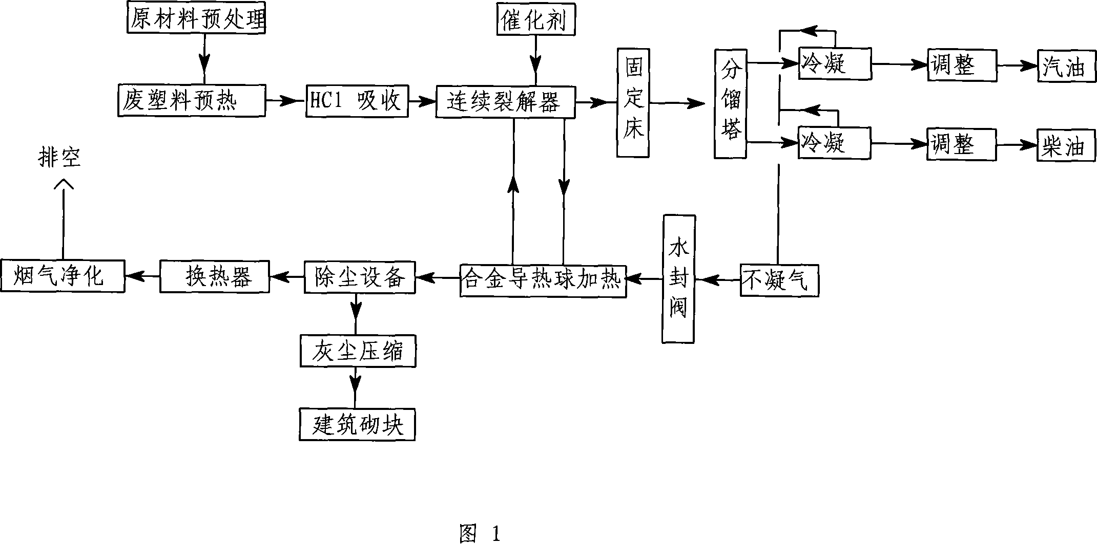
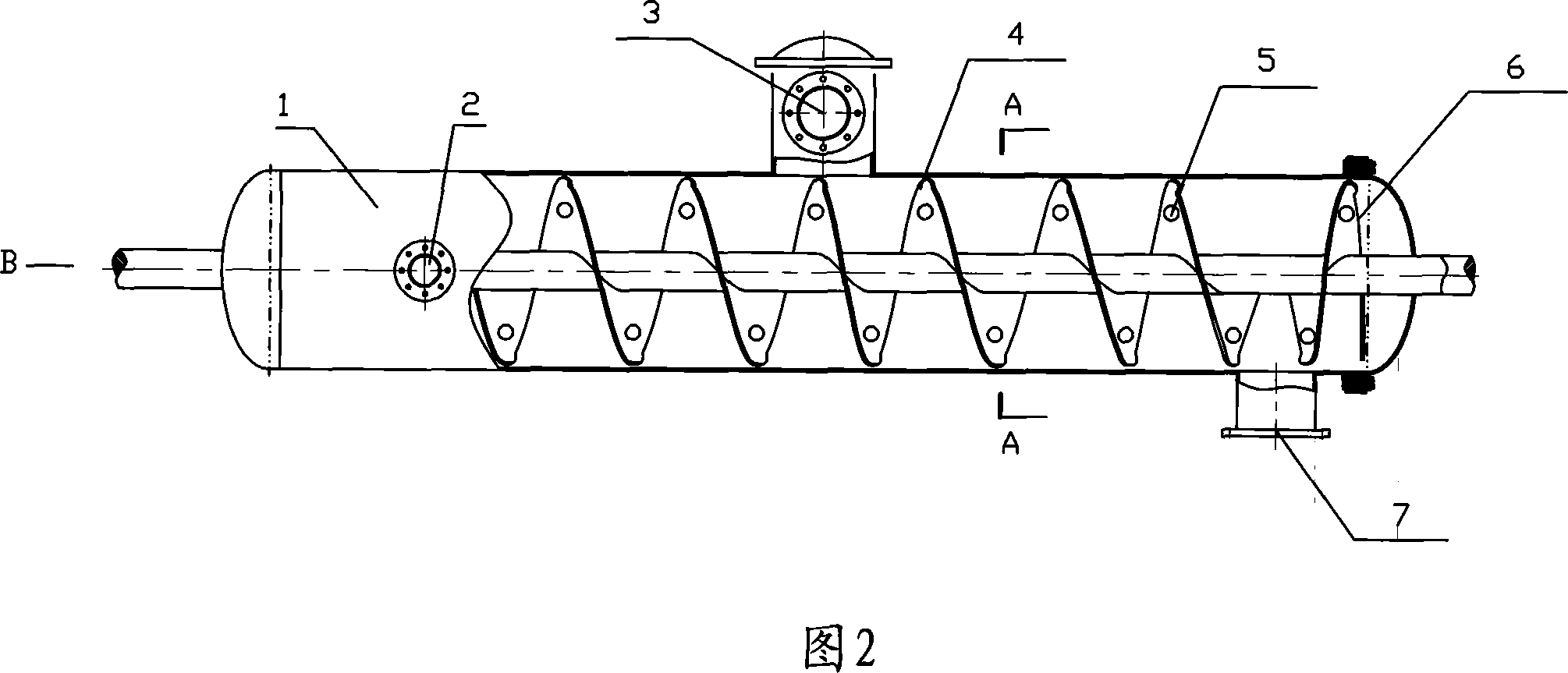
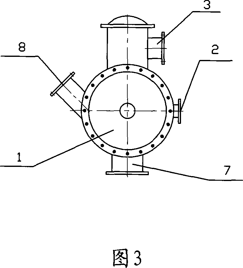
[0031] After the waste plastics are pretreated, put them into the preheating system for preheating to make them molten, and then pass through the alkaline absorption tower to absorb the generated HCl, and the molten waste plastics are passed into the cracker at a rate of 1 ton per hour. Add a conventional plastic cracking catalyst, the thermal ball moves in the same direction as the waste plastic in the pyrolyzer and mixes it to crack the waste plastic. The screw propulsion mechanism in the device provides power for the movement of the raw material and the solid heat carrier in the same direction, and mixes the heat conduction ball and the molten waste plastic; the gas obtained from the cracking is subjected to secondary cracking through the fixed catalytic bed, and the secondary cracking gas passes through fractionation Tower, the obtained fractions are condensed and adjusted to obtain gasoline, diesel oil and other oil products; the condensed non-condensable gas is purified a...
Embodiment 2
[0033] Put the waste plastic into the preheating system for preheating to make it molten, and then absorb the generated HCl through the alkaline absorption tower. The molten waste plastic is passed into the cracker at a rate of 1.5 tons per hour, and the ceramic ball The speed of 44 tons per hour is passed into the cracker in the same direction as the waste plastic and mixed with it to crack the waste plastic. The temperature of the ceramic ball is 400-460 ° C. The screw propulsion mechanism in the cracker provides the raw material and ceramic ball with the same direction. Power; the gas obtained from cracking passes through the fractionation tower, and the obtained fractions are condensed and adjusted to obtain gasoline, diesel and other oil products; the condensed non-condensable gas is passed into a solid heat carrier heating device for combustion, and after combustion, it passes through a multi-stage purification device and is emptied. Other equipment and technology adopt e...
Embodiment 3
[0035] Pass the waste plastics into the cracker at a rate of 0.5 tons per hour, and add a catalyst at the same time, and the solid heat carrier passes into the cracker at the same speed as the waste plastics at a rate of 30 tons per hour and mixes with it to crack the waste plastics. The temperature of the solid heat carrier is 420-440 ° C. The screw propulsion mechanism in the cracker provides power for the movement of the raw material and the solid heat carrier in the same direction; the gas obtained from the cracking is subjected to secondary cracking through the fixed catalytic bed, and the secondary cracked gas passes through the fractionation tower , the resulting fractions are condensed and adjusted to obtain gasoline, diesel oil and other oil products; the condensed non-condensable gas is purified and sealed, and then passed into a solid heat carrier heating device for combustion. The solid products of the cracker are discharged, and the high-temperature flue gas after ...
PUM
| Property | Measurement | Unit |
|---|---|---|
| Diameter | aaaaa | aaaaa |
| Diameter | aaaaa | aaaaa |
| Diameter | aaaaa | aaaaa |
Abstract
Description
Claims
Application Information