
Power-supplying circuit with zero-static consumption induction controlled

A power supply control circuit and method control technology, applied in the direction of battery circuit devices, circuit devices, collectors, etc., can solve problems such as poor shock resistance and reliability, accidental on-off of contact points, and influence on popularization and use, etc., to achieve long working distance, Effect of improving reliability, reducing size and cost

Inactive Publication Date: 2007-11-21
TSINGHUA UNIV +1
View PDF0 Cites 21 Cited by
  • Summary
  • Abstract
  • Description
  • Claims
  • Application Information

AI Technical Summary

Problems solved by technology

However, this power supply method has a large volume, poor earthquake resistance and reliability, which is not conducive to transportation, which affects its further promotion and use.
For example, in the current wireless endoscope capsule, a magnetically controlled reed switch is used to control the power supply of its internal system. During product transportation, due to vibration, the contact point will be accidentally turned on and off, so that the battery power of the capsule will be reduced before use. May be consumed, resulting in insufficient energy in the capsule to test the small intestine

Method used


Image

  • Power-supplying circuit with zero-static consumption induction controlled
  • Power-supplying circuit with zero-static consumption induction controlled
  • Power-supplying circuit with zero-static consumption induction controlled

Examples


Embodiment Construction

[0026] The composition of the power supply control circuit of the present invention and the working process of the portable electronic device adopting the present invention will be described in detail below in conjunction with the drawings and embodiments.

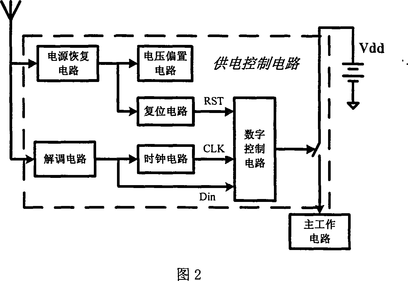
[0027] The overall structure of the power supply control circuit for portable electronic equipment designed by the present invention is shown in the dotted line box in Figure 2, including a power recovery circuit, a voltage bias circuit, a demodulation circuit, a clock circuit, a reset circuit, a digital control circuit, and control switch; the connection relationship of each circuit is: the power supply recovery circuit is connected with the input terminals of each circuit respectively (the connection lines with some circuits are omitted in the figure), and the output terminal of the voltage bias circuit is connected with the demodulation circuit, reset circuit, respectively. The input terminals of the circuit and the cloc...


PUM


Abstract

The invention comprises: a power restoring circuit; a voltage biasing circuit, a demodulation circuit, a clock circuit, a reset circuit, a digital control circuit and a controllable switch. The power restoring circuit is respectively connected to the input end of each circuit; the output of the voltage biasing circuit is respectively connected to the input end of the demodulation circuit, reset circuit, and clock circuit; the output end of the demodulation circuit is respectively connected to the input end of the clock circuit and the digital control circuit; the output end of the reset circuit and clock circuit is connected to the input end of digital control circuit; the output end of the digital control circuit is connected to the controllable switch.

Description

technical field [0001] The invention belongs to the field of analog signal processing, in particular to the structural design of a power supply circuit in a battery-powered portable electronic device. Background technique [0002] Portable electronic devices are widely used in today's society, such as paper tape cameras, radio frequency identification tags, etc. The key factors affecting the large-scale application of portable electronic devices are their production cost and working life, and the power supply capacity of their batteries has become an important link to ensure the long-term use of such devices. [0003] Common portable electronic devices are divided into two types: passive and active, each of which has its own application background. The passive device does not contain a battery inside and has zero static power consumption. It uses electromagnetic waves emitted by an external reader to provide energy. The advantages are small size, long life, and low cost. Th...

Claims


Application Information

Patent Timeline
IPC IPC(8): H02J7/00H02J17/00H02M7/25G08C17/02H02J50/20
Inventor 高同强张春王志华
Owner TSINGHUA UNIV
Learn More