Minisize highly-effective thermal self-circulation cooling system for fuel cell

A fuel cell and cooling system technology, used in fuel cell heat exchange, fuel cells, fuel cell additives, etc., can solve the problem of reducing the weight specific power and volume specific power of the fuel cell stack system, reducing the efficiency of the fuel cell system, limiting fuel Battery use occasions and other issues, to achieve the effect of improving the overall use efficiency, environmental protection, and light weight

Inactive Publication Date: 2007-12-05
SOUTH CHINA UNIV OF TECH
View PDF0 Cites 13 Cited by
  • Summary
  • Abstract
  • Description
  • Claims
  • Application Information

AI Technical Summary

Problems solved by technology

This undoubtedly increases the volume of the cooling system, thereby reducing the weight-specific power and volume-specific power of the entire fuel cell stack system
[0004] (2) Due to the large size of the entire battery system, its application is greatly restricted, and it is difficult to use it in laptops, cameras, electric tools, electric bicycles, electric scooters, electric wheelchairs, electric vehicles, electric vehicles, etc. Portable electronic and electrical equipment such as lawn mowers, as well as mobile vehicles and machines
[0005] (3) When using a water cooling system to cool the fuel cell, due to the small temperature difference between the water inlet and the water outlet, not only a large amount of water is required to participate in the circulating cooling process, but also a large heat transfer area and volume are required to meet the needs of heat removal, making it difficult to arrange when used on mobile appliances
[0006] (4) When the air cooling system is used to cool the fuel cell, due to the low heat transfer efficiency, it can only be used to control the fuel cell stack system with a low operating temperature (30-50°C)
Therefore, when the working temperature is too low, the catalytic activity of the catalyst is very low, and the output power of the entire battery system is also very low.
[0007] (5) Additional power is required to drive mechanical devices such as circulation pumps and fans, which also reduces the overall efficiency of the fuel cell system
[0008] (6) In addition, these mechanical devices will generate a lot of noise during operation, which will further limit the use of fuel cells

Method used


Image

  • Minisize highly-effective thermal self-circulation cooling system for fuel cell
  • Minisize highly-effective thermal self-circulation cooling system for fuel cell
  • Minisize highly-effective thermal self-circulation cooling system for fuel cell

Examples


Embodiment 1

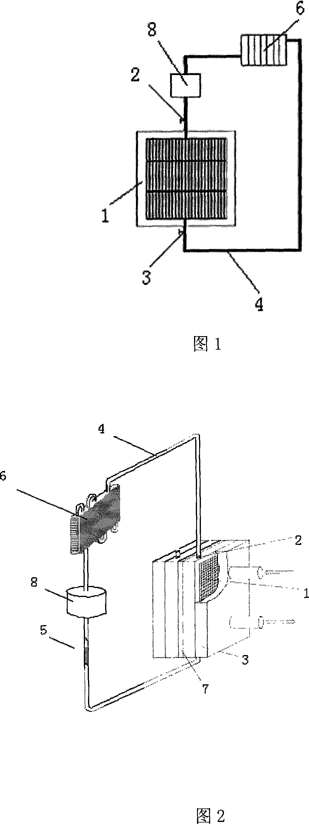
[0034] As shown in Figures 1 and 2, the fuel cell miniature high-efficiency thermodynamic self-circulation cooling system consists of a metal bipolar plate 1 with a micro-channel evaporator in the inner cavity, and a condensation pipe 4. The condensation pipe 4 passes through a unidirectional conduction function. The inlet micro-check valve 3 and the outlet micro-check valve 2 are in communication with the micro-channel, the condensing pipe 4 and the micro-channel have circulating cooling working medium 5, and the condensing pipe 4 is provided with heat-dissipating metal fins 6 and connected with a cooling Working fluid storage tank 8.

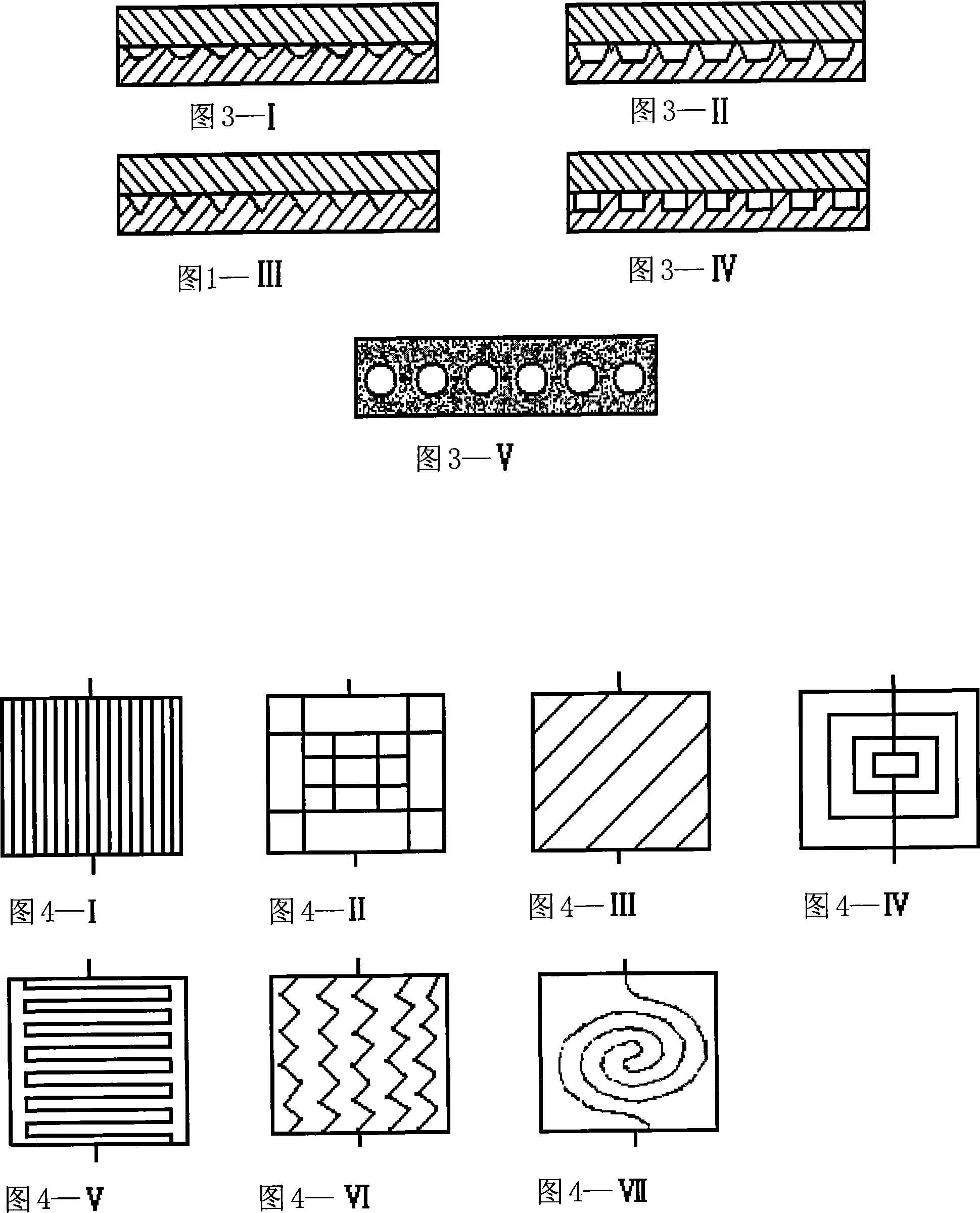
[0035] The microchannel in the inner cavity of the bipolar plate 1 is to process some micro channels with a width of 1 mm and a depth of 1 mm on the surface of a stainless steel plate, and its cross-sectional shape is square, as shown in Figure 3-IV, and then bonded with another side surface There is a combination package of stainless steel pl...

Embodiment 2

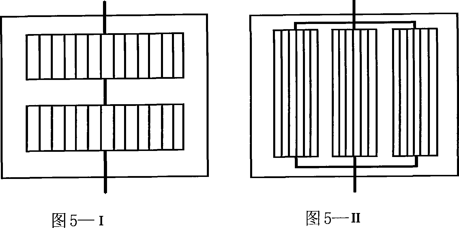
[0037]The structure of the fuel cell miniature high-efficiency thermodynamic self-circulating cooling system is the same as that of Embodiment 1. Wherein the microchannel in the inner cavity of the bipolar plate 1 is to process some microchannels with a radius of 0.5mm on the surface of an aluminum plate first, and its cross-sectional shape is shown in Figure 3-I, and the other side has a serpentine gas flow channel. The combination of the reverse side of the aluminum plate is used to seal the two plates with a silicone rubber wire. As shown in Figure 5-I, multiple groups of microchannels are connected in series through fine grooves whose cross-sectional area is 2 to 3 times the cross-sectional area of ​​the microchannels, as shown in Figure 4-II, the arrangement of each group of microchannels adopts a well-shaped pattern. The condensation tube is a stainless steel capillary with a diameter of 3 mm and a wall thickness of 1 mm. The micro-check valve is a micro-check valve pro...

Embodiment 3

[0039] The structure of the fuel cell miniature high-efficiency thermodynamic self-circulating cooling system is the same as that of Embodiment 1. Among them, the microchannels in the inner cavity of the bipolar plate are processed on the surface of a copper plate with some micro channels with a height of 1 mm and a width of 1 mm at the bottom. The cross-sectional shape is shown in Figure 3-III. The reverse side of the red copper plate of the flow channel is combined and packaged, and the two plates are sealed with a silicone rubber wire. As shown in Figure 5-II, multiple groups of microchannels can be connected in parallel through fine grooves whose cross-sectional area is 2 to 3 times the cross-sectional area of ​​the microchannels, as shown in Figure 4-III, the arrangement of each group of microchannels is oblique. Copper capillary with a diameter of 3 mm and a wall thickness of 1 mm was used as the condenser tube. The micro-check valve is a micro-check valve produced by L...


PUM

PropertyMeasurementUnit
boiling pointaaaaaaaaaa

Abstract

The invention provides a fuel cell micro high-efficiency thermo-operated self-circulating cooling system, comprising: bipolar plate whose inner cavity is provided with microchannel evaporator, and condenser tube, where the condenser tube is connected with the microchannel via inlet and outlet micro check valves having one-way turn-on function, and there is circulating cooling medium inside the condenser tube and the microchannel, and according to the requirement for cooling and heat discharge, the condenser tube is also provided with heat radiation fins, and connected with cooling working medium storage cylinder. And it has good heat radiation effect, simpler structure and higher total utilization ratio of cell stack, and applies to low temperature fuel cell stacks such as PEMFC, and DMFC.

Description

technical field [0001] The invention relates to a heat radiation cooling system of a fuel cell, in particular to a miniature high-efficiency thermodynamic self-circulation cooling system of a fuel cell. Background technique [0002] When the fuel cell is running, its energy conversion efficiency is about 40% to 60%, and another 60% to 40% of the energy is discharged out of the battery stack in the form of waste heat to maintain a constant operating temperature of the battery. At present, there are mainly two heat removal methods widely used in fuel cells: one is to remove heat through cooling water circulation. This method generally requires a mechanical circulation pump to promote the circulation of cooling water in the entire cooling circuit, and take away the waste heat inside the battery stack through the circulation of cooling water; the other is the air cooling used in low output power fuel cells Exhaust heat. This method generally requires a blower or an exhaust fan...

Claims


Application Information

Patent Timeline
Patent Type & Authority Applications(China)
IPC IPC(8): H01M8/02H01M8/04014H01M8/04029
CPCY02E60/50
Inventor 周震涛张俊于非
Owner SOUTH CHINA UNIV OF TECH
Why Eureka
Try Eureka