Thin plate combined type photocatalyst carrier structure

A photocatalyst and combined technology, which is applied in the direction of catalyst carrier, physical/chemical process catalyst, chemical instrument and method, etc., can solve the problems that can no longer provide surface area, affect the photocatalytic efficiency of the system, and cannot be irradiated by ultraviolet light.

Inactive Publication Date: 2008-01-02
杨小明
View PDF0 Cites 18 Cited by
  • Summary
  • Abstract
  • Description
  • Claims
  • Application Information

AI Technical Summary

Problems solved by technology

[0004] In the existing photocatalyst processor, some commonly used carriers include metal foam, porous ceramic material, aluminum honeycomb filter screen, wire mesh, non-woven fabric, etc. These carriers have a high specific surface area, but these carriers themselves are There are many small branches in the shape of filaments, strips, blocks, and sheets that are interlaced and combined. These small branches in the form of filaments, strips, blocks, and sheets overlap and block each other. When irradiated with ultraviolet light When using a linear (column) light source (such as a straight ultraviolet lamp tube), in fact, due to the linear propagation characteristics of light, only the small branch blocks on the outermost side close to the light source can be irradiated by ultraviolet light, while The backlight surface of the small branch and many other small branches in the shadow formed by these small branches irradiated by ultraviolet light cannot be irradiated by ultraviolet light, so that the photocatalyst on it cannot be effectively excited. It affects the photocatalytic efficiency of the system, so the effective surface area of ​​these photocatalysts on photocatalyst carriers with high specific surface area is very small when irradiated by ultraviolet rays.
Therefore, under a certain volume, the above-mentioned carrier can no longer provide more effective surface area that can be irradiated by ultraviolet rays, forming a bottleneck that is difficult to break through in the practical application of this photocatalyst technology.

Method used


Image

  • Thin plate combined type photocatalyst carrier structure
  • Thin plate combined type photocatalyst carrier structure
  • Thin plate combined type photocatalyst carrier structure

Examples


Embodiment Construction

[0035] In order to better understand the above technical solutions of the present invention, a further detailed description will be given below in conjunction with the drawings and embodiments.

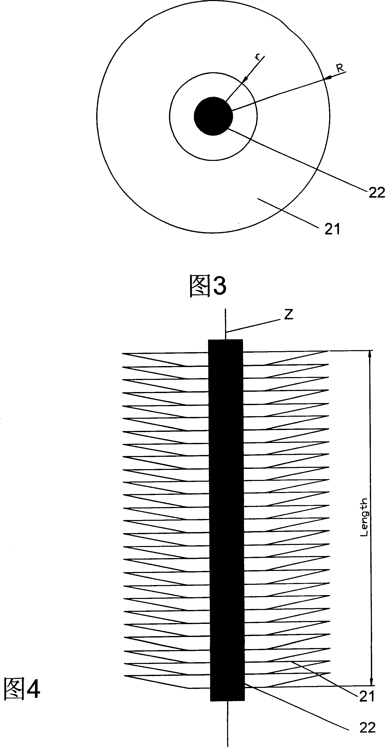
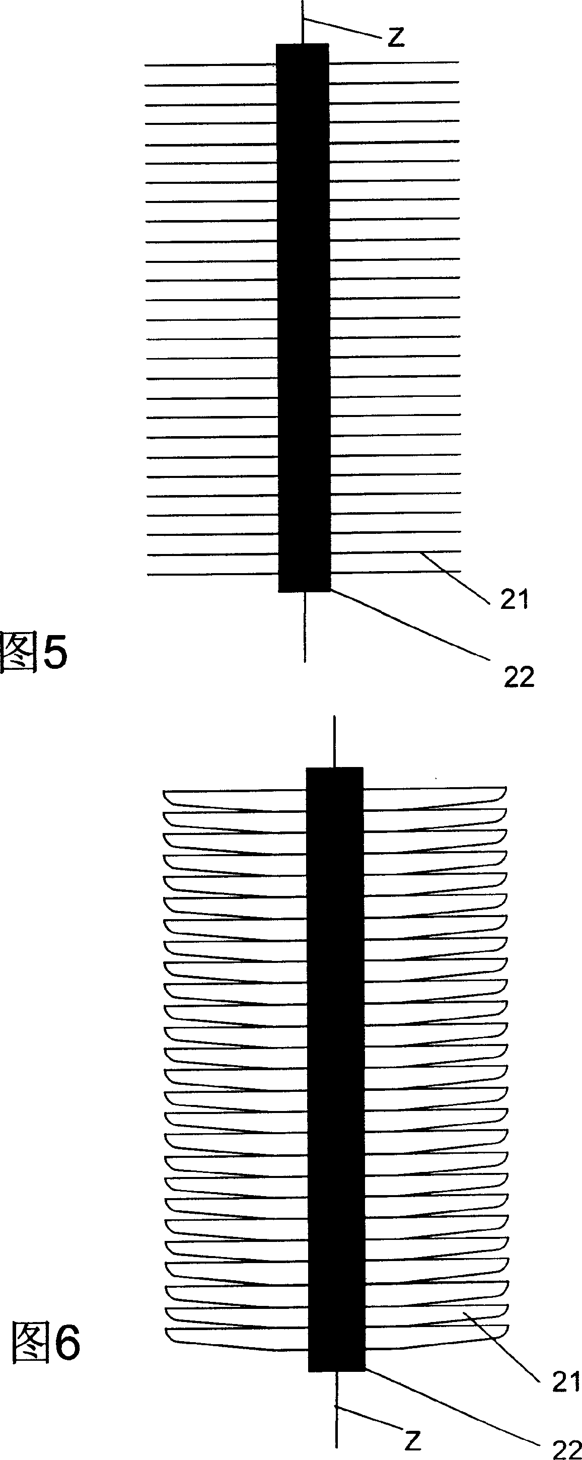
[0036] Please refer to Fig. 3, shown in Fig. 4 first, thin-plate combined type photocatalyst carrier structure of the present invention comprises several thin plates 21, ultraviolet light source 22,

[0037] The several thin plates 21 are arranged and combined together in layers along the vertical axis Z direction of the ultraviolet light source 22, the ultraviolet light source 22 passes through the middle part of the several thin plates 21, and the surface of each thin plate 21 is loaded with a photocatalyst. Gaps for fluid flow are left between the thin plates 21 for the fluid to flow in these gaps.

[0038] The thin plate 21 is a plane plate or a revolving panel, and the revolving line of the revolving panel is any one of a straight line, an arc line, a folding line, and a bending ...


PUM


Abstract

The invention discloses a thin-plate combined photocatalyst carrier structure, comprising several thin plates and ultraviolet light source. Several thin plates are arranged in laminated shape on the vertical axis direction of ultraviolet light source. Ultraviolet light source passes through the middle part among thin plates. Photocatalyst is carried on the surface of each thin plate and gaps for fluid flow are provided among thin plates. The photocatalyst carrier structure can make full use of linear propagation characteristic of ultraviolet light and make photocatalyst carrier obtain ultra-large ultraviolet irradiation ratio surface area. At the same time by adding the number of thin plates or developing blade dimension of thin plate arranging position of thin plate can be adjusted correspondingly to obtain larger ultraviolet irradiation ratio surface area. After the thin-plate combined photocatalyst carrier structure is applied in contamination treatment system, higher treating efficiency can be obtained. The invention provides technical support for practical application of contamination treatment system by photocatalyst. At the same time invest and use costs of treatment system are decreased.

Description

technical field [0001] The invention relates to components in a photocatalyst processor for filtering pollutant fluids, and more specifically refers to a thin-plate combined photocatalyst carrier structure. Background technique [0002] The photocatalytic properties of photocatalysts (such as nano-titanium dioxide) were discovered by Professor Fujiyu Akira in Japan in 1972, and have been extensively studied and applied so far. The basic principle of photocatalysis is: when semiconductor oxide (such as titanium dioxide) nanoparticles are irradiated by photons (such as ultraviolet light) with energy greater than the forbidden band width, electrons transition from the valence band to the conduction band, generating electron-hole pairs. Electrons are reducing, and holes are oxidizing. Holes react with OH- on the surface of oxide semiconductor nanoparticles to generate highly oxidizing OH radicals. Active OH radicals can oxidize many refractory organic compounds into CO2 and Ino...

Claims


Application Information

Patent Timeline
Patent Type & Authority Applications(China)
IPC IPC(8): B01J32/00
Inventor 杨小明
Owner 杨小明
Why Eureka
Try Eureka