Method for depositing magnetic film on flexible substrate
A magnetic thin film and flexible substrate technology, applied in metal material coating process, ion implantation plating, coating, etc., can solve the problems of waste of raw materials, long time consumption, etc., and achieve the effect of reducing serious pollution
- Summary
- Abstract
- Description
- Claims
- Application Information
AI Technical Summary
Problems solved by technology
Method used
Image
Examples
Embodiment 1
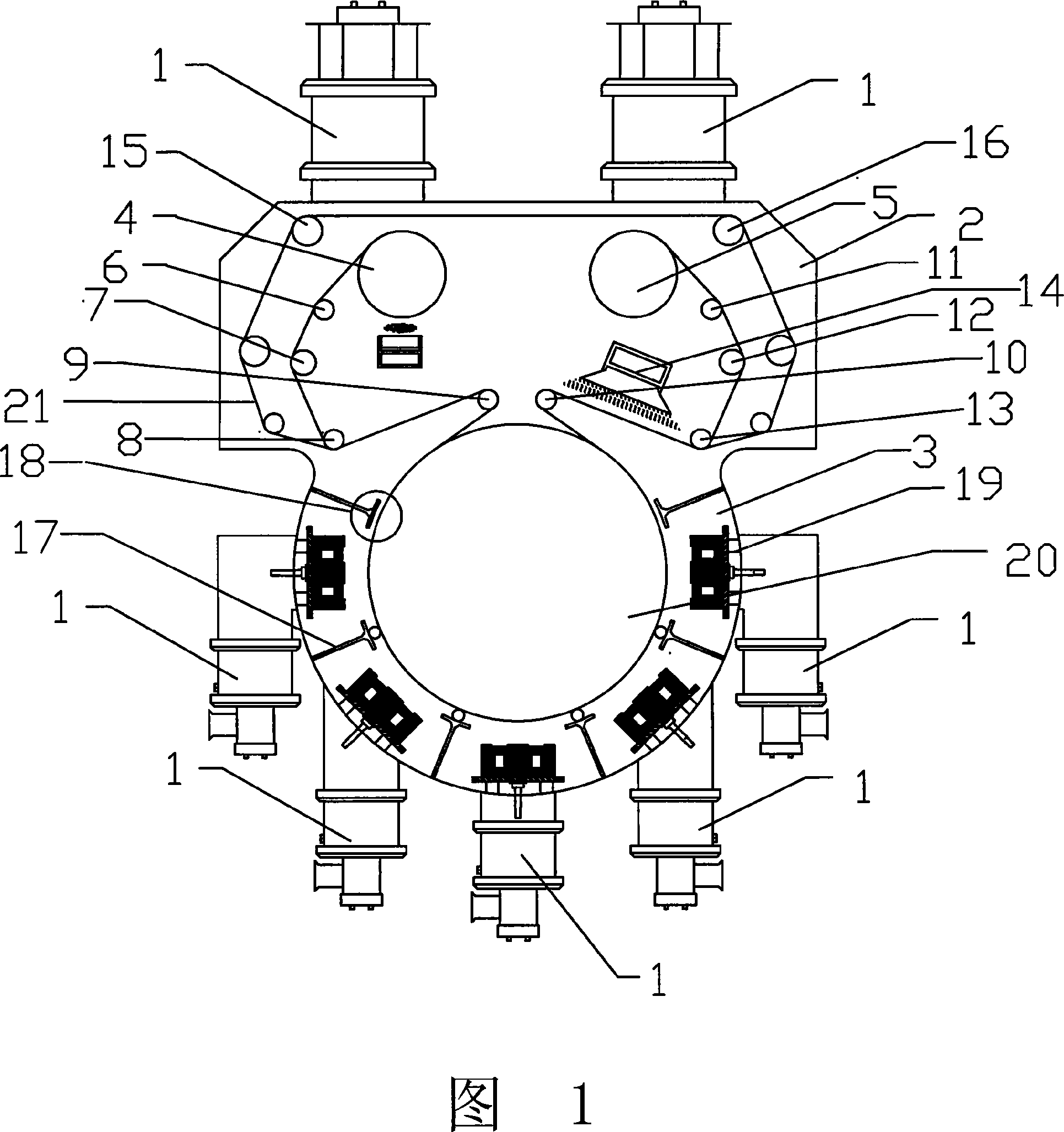
[0035] The flexible substrate selected in this embodiment is paper, which is continuously unwound by the unwinding roller 4, and the paper is conveyed to the coating chamber 3 by the guide rollers 6 and 7, the tension roller 8 and the pressing roller 9. The synchronous travel of the mask plate and the substrate provided with the barcode pattern in the working direction and the vertical working direction is realized by three guide rollers such as the guide roller 15 , and the tension roller 8 and the pressure roller 9 . After passing through the above-mentioned overall transmission, the paper and the mask plate enter the coating chamber. After entering the coating chamber, the paper is closer to the cooling roller and the mask is closer to the target chamber. Fe-Mo-Mn-B-Si alloy targets are installed in the five target chambers, so that when the mask and the paper run synchronously along the working direction (x direction), the thin film deposition interval of each target chamb...
Embodiment 2
[0037] The flexible substrate selected in this embodiment is paper, which is continuously unwound by the unwinding roller 4, and the paper is conveyed to the coating chamber 3 by the guide rollers 6 and 7, the tension roller 8 and the pressing roller 9. The synchronous travel of the mask plate and the substrate provided with the barcode pattern in the working direction and the vertical working direction is realized by three guide rollers such as the guide roller 15 , and the tension roller 8 and the pressure roller 9 . After passing through the above-mentioned overall transmission, the paper and the mask plate enter the coating chamber. After entering the coating chamber, the paper is closer to the cooling roller and the mask is closer to the target chamber. Fe-Mo-Mn-B-Si alloy targets are installed in the three target chambers, so that when the mask and the paper run synchronously along the working direction (x direction), the thin film deposition interval of each target cham...
Embodiment 3
[0039] The flexible substrate selected in this embodiment is PET, which is continuously unwound by the unwinding roller 4, and the PET is conveyed to the coating chamber 3 by the guide rollers 6 and 7, the tension roller 8 and the pressing roller 9. The synchronous travel of the mask plate and the substrate provided with the barcode pattern in the working direction and the vertical working direction is realized by three guide rollers such as the guide roller 15 , and the tension roller 8 and the pressure roller 9 . After passing through the above-mentioned overall transmission, PET and mask board enter the coating chamber. After entering the coating chamber, the PET is close to the cooling roll and the mask plate is closer to the target chamber. Fe-Mo-Mn-B-Si alloy targets are installed in the three target chambers, so that when the mask and PET run synchronously along the working direction (x direction), the film deposition interval of each target chamber At the same time, t...
PUM
 Abstract
Description
Claims
Application Information
 - R&D
- Intellectual Property
- Life Sciences
- Materials
- Tech Scout
- Unparalleled Data Quality
- Higher Quality Content
- 60% Fewer Hallucinations
Browse by: Latest US Patents, China's latest patents, Technical Efficacy Thesaurus, Application Domain, Technology Topic, Popular Technical Reports.
© 2025 PatSnap. All rights reserved.Legal|Privacy policy|Modern Slavery Act Transparency Statement|Sitemap|About US| Contact US: help@patsnap.com


