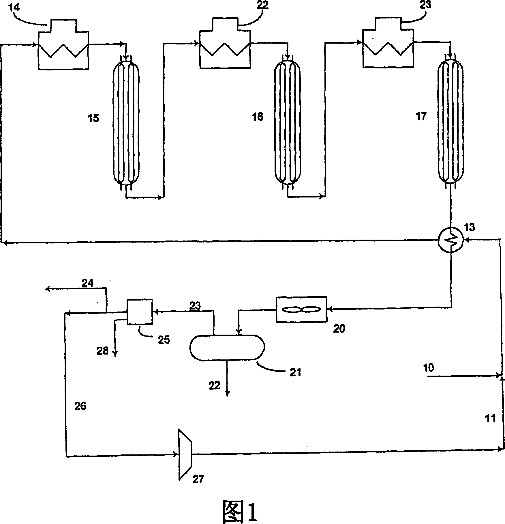
Improved catalytic reformer unit and unit operation
A technology for catalytic reforming and reforming catalysts, which is applied in the direction of catalytic reforming of naphtha, control/regulation of reforming operations, reforming naphtha, etc., and can solve problems such as reducing reformed products and hydrogen yields
- Summary
- Abstract
- Description
- Claims
- Application Information
AI Technical Summary
Problems solved by technology
Method used
Image
Examples
Embodiment 1
[0063] In this example, the refinery stream is 480 psig and the tail gas is 65 psig, resulting in a pressure change of 6.18. Feed compositions and pressures are common to refinery processing units such as those found in hydroprocessing or hydroprocessing applications. In this example, hydrocarbons are generally described by their carbon number, ie C 1 = methane, C 2 = Ethane, etc. RCPSA is capable of producing >99% pure hydrogen with >81% recovery over a range of flow rates. Tables 1a and 1b present the computer simulation results for RCPSA, and the feed and output percentages for the different components of this example. Tables 1a and 1b also show how hydrogen purity decreases as recovery increases from 89.7% to 91.7% for a 480 psig 6 MMS CFD stream and 65 psig tail gas.
[0064] Tables 1a and 1b
[0065] in H 2 RCPSA in decontamination (67 feet 3 ) feed and output composition (mol%).
[0066] The feed was 480 psi, 122 degrees Fahrenheit, and the exhaust was 65 psi. ...
Embodiment 2
[0078] In this example, the conditions are the same as in Example 1. Table 2a shows that conditions using both co-current and counter-current steps achieve >99% hydrogen purity. Table 2b shows that the countercurrent depressurization step can be eliminated and still maintain a hydrogen purity of 99%. In fact, it can be seen that by increasing the purge cycle time t P , by removing the time t from the countercurrent depressurization step CN , the hydrogen recovery can be increased to a level of 88%.
[0079] Table 2a and 2b
[0080] Step duration for RCPSA (67 ft. 3 ) of H 2 Effect on purity and recovery.
[0081] Same conditions as in Table 1. The feed was 480 psi, 122 degrees Fahrenheit, and the exhaust was 65 psi. The feed rate is approximately 6 MMSCFD.
[0082] Table 2a. Countercurrent Reduced Pressure, Medium Pressure = 105 psi
[0083] purity
Recovery rate
t F
t co
t CN
t P
t RP
%
% ...
Embodiment 3
[0087] This example represents a refinery stream of 10 MMSCFD, also containing a typical composition as shown in the feed column of Table 3 (e.g. the feed composition contains 74% H 2 ). The stream is 480 psig, the RCPSA tail gas is 65 psig, so the absolute pressure becomes 6.18. Also the RCPSA of the present invention is capable of producing hydrogen at >99% purity with >85% recovery from these feed compositions. Tables 3a and 3b show the results of this example.
[0088] Tables 3a and 3b
[0089] in H 2 RCPSA in decontamination (53 feet 3 ) feed and output composition (mol %). The feed was 480 psi, 101 degrees Fahrenheit, and the exhaust was 65 psi.
[0090] The feed rate is about 10 MMSCFD.
[0091] Table 3a. Higher Purity
[0092] Step time (seconds) t F =0.583,t co =0.083,t CN = 0, t P =0.25,t RP =0.25
[0093] H2 purity 99.98%, recovery 86%
[0094] 86% recovery
[0095] Feed
product
Exhaust
H2
C1
C2
C3
C...
PUM
| Property | Measurement | Unit |
|---|---|---|
| recovery rate | aaaaa | aaaaa |
| recovery rate | aaaaa | aaaaa |
| recovery rate | aaaaa | aaaaa |
Abstract
Description
Claims
Application Information
 - R&D
- Intellectual Property
- Life Sciences
- Materials
- Tech Scout
- Unparalleled Data Quality
- Higher Quality Content
- 60% Fewer Hallucinations
Browse by: Latest US Patents, China's latest patents, Technical Efficacy Thesaurus, Application Domain, Technology Topic, Popular Technical Reports.
© 2025 PatSnap. All rights reserved.Legal|Privacy policy|Modern Slavery Act Transparency Statement|Sitemap|About US| Contact US: help@patsnap.com

