Laser heating device and laser heating method

A laser heating and laser technology, which is applied in the direction of semiconductor laser optical devices, lasers, measuring devices, etc., can solve the problem that the temperature of the heated object cannot be measured, and achieve the effect of stable temperature control

Inactive Publication Date: 2008-01-16
PANASONIC CORP
View PDF1 Cites 19 Cited by
  • Summary
  • Abstract
  • Description
  • Claims
  • Application Information

AI Technical Summary

Problems solved by technology

[0003] However, in heating processing using laser light, the temperature of the object to be heated increases as long as the laser light is continuously ir

Method used


Image

  • Laser heating device and laser heating method
  • Laser heating device and laser heating method
  • Laser heating device and laser heating method

Examples


Embodiment Construction

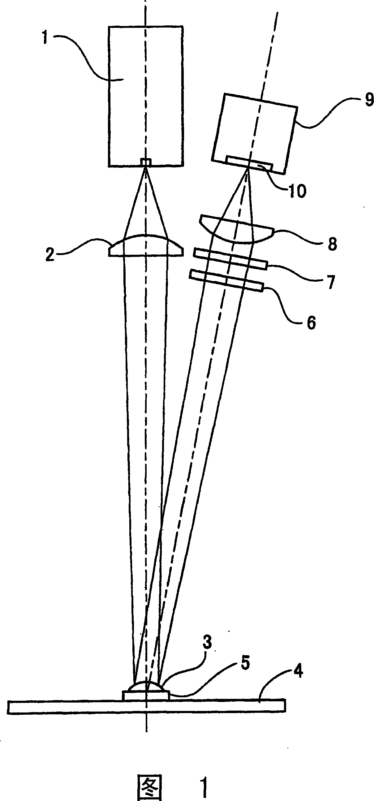
[0046] Hereinafter, a laser heating device and a laser heating method according to embodiments of the present invention will be described with reference to the drawings.

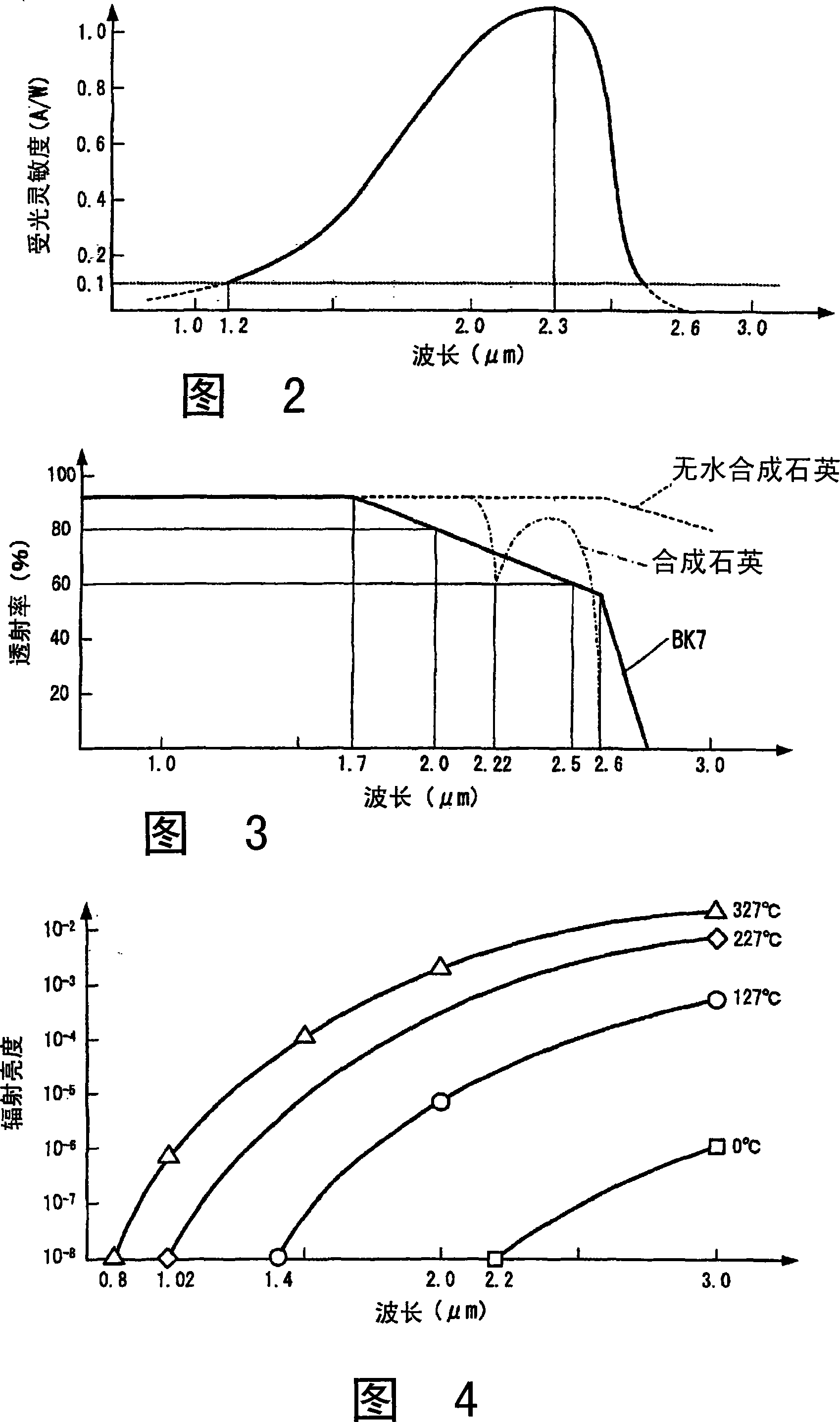
[0047] In the following embodiments, an infrared sensor is provided that generates a signal based on an integrated value of the spectral radiance of infrared rays received by the light receiving surface. Furthermore, before performing the laser heating processing, the relational expression of the calibration value of the output signal of the said infrared sensor and the actual measurement temperature of the object to be heated for calibration is calculated|required in advance. Then, when the laser heating processing is actually performed, among the light radiated or reflected from the object to be heated and its peripheral portion, infrared rays other than the light of the wavelength of the laser light are guided to the light receiving surface of the infrared sensor, The temperature of the object to be heate...


PUM


Abstract

A laser heating device and a laser heating method enabling soldering that does not burn the periphery and resin bonding that does not burn resin by detecting a temperature change when solder or resin at a processing point is melted and an abnormal heating that may indicate a possible burn occurrence. An IR sensor (9) generates a signal based on the integrated value of the spectral radiation luminance of an IR ray radiated from solder to be heated. Prior to an actual soldering, a relational expression between the calibration values of an output signal from the IR sensor (9) and an actual master solder measuring temperature is determined in advance. At an actual soldering, an IR ray radiated from solder (3) is received by the IR sensor (9) and the temperature of the solder (3) is calculated based on an output signal from the IR sensor (9) and the above relational expression.

Description

technical field [0001] The present invention relates to a laser heating device and a laser heating method for performing heat processing such as soldering, resin bonding, or welding, for example, using laser light emitted from a semiconductor laser. Background technique [0002] Conventionally, as a laser heating device for non-contact heating processing using laser light, for example, a device has been proposed, which consists of a laser diode module (semiconductor laser array) formed by stacking a plurality of laser diodes, The emitted laser light is configured by a collimator lens for collimating (collimating) the laser beam and a focusing lens for focusing the collimated laser light (for example, refer to JP2002-9388A). According to this configuration, the conventional laser heating device can heat-process the object to be heated placed at the focal position of the focusing lens. [0003] However, in the heating process using laser, as long as the laser irradiation ...

Claims


Application Information

Patent Timeline
IPC IPC(8): G01J5/08B23K26/00H01S5/00B23K26/03B23K26/073B23K101/42G01J1/02G01J5/00G01J5/28
CPCG01J5/08G01J5/025G01J5/0846B23K2201/42G01J5/0003G01J5/089G01J5/084G01J5/0018G01J5/0862B23K26/0807G01J5/0806B23K26/0608G01J5/0859B23K1/0016G01J5/602G01J5/06B23K26/067H01S5/005H01S5/4025B23K26/03G01J5/02B23K26/0604B23K1/0056G01J5/004B23K26/082B23K2101/42G01J5/0802G01J5/07
Inventor 樱井努船见浩司
Owner PANASONIC CORP
Why Eureka
Try Eureka