Radiant heater for heating the building material in a laser sintering device

A radiation heater, laser sintering technology, applied in the field of radiation heaters, can solve the problem of no rapid temperature control or adjustment

Inactive Publication Date: 2008-01-16
EOS ELECTRO OPTICAL SYST
View PDF2 Cites 22 Cited by
  • Summary
  • Abstract
  • Description
  • Claims
  • Application Information

AI Technical Summary

Problems solved by technology

Thereby, especially at lower temperatures, no rapid temperature control or regulation is possible

Method used


Image

  • Radiant heater for heating the building material in a laser sintering device
  • Radiant heater for heating the building material in a laser sintering device
  • Radiant heater for heating the building material in a laser sintering device

Examples


Embodiment Construction

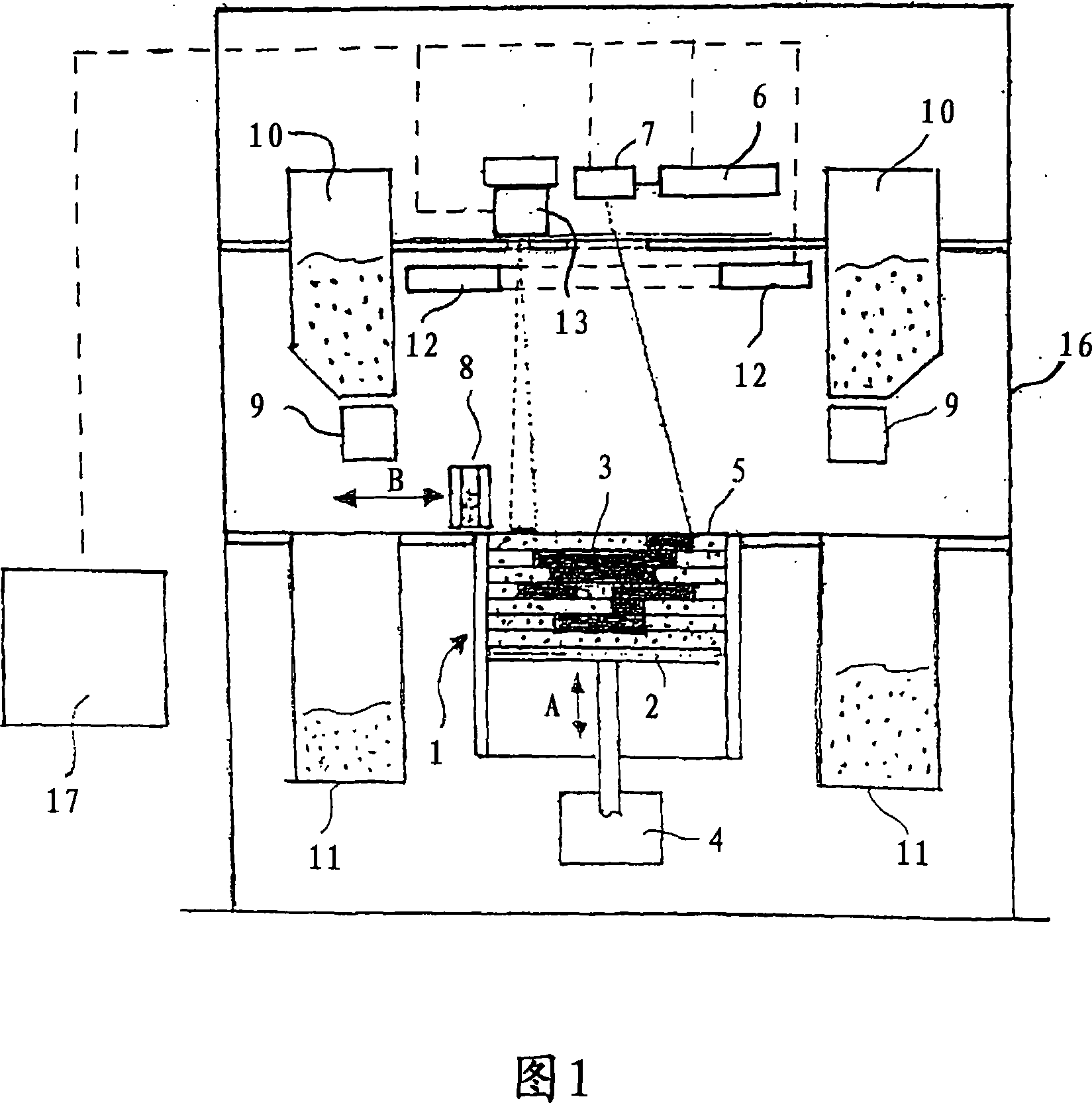
[0019] FIG. 1 shows a laser sintering device with radiation heating according to the invention. The laser sintering device includes a container 1 that is open upwards. Arranged in the container 1 is a support 2 for supporting an object 3 to be formed. The support 2 can be moved up and down in the vertical direction A in the container 1 by means of a drive device 4 . The upper edge of the container 1 defines a working surface 5 . An irradiation device 6 in the form of a laser is located above the working surface 5 and emits a directed laser beam which is deflected onto the working surface 5 by means of a deflection device 7 . Furthermore, an application device 8 is provided for applying a layer of powder material to be cured onto the surface of the support 2 or a layer that is finally cured. The coating device can be moved back and forth on the working surface 5 by a drive device, which is schematically indicated by arrow B. The coating device 8 is fed by two powder storage...


PUM

PropertyMeasurementUnit
thicknessaaaaaaaaaa
thicknessaaaaaaaaaa

Abstract

The invention relates to a radiant heater for heating the building material in a laser sintering device and to a laser sintering device comprising a radiant heater of this type. The radiant heater comprises a flat heat-emission element (113, 213, 313), which is characterised in that it consists of a material with low thermal inertia and a thermal diffusivity preferably in excess of 1.5 10-4 m2 / s and preferably a thickness less than or equal to 2 mm.

Description

technical field [0001] The invention relates to a radiation heater according to the preamble of claim 1 and to a laser sintering device with such a radiation heater. Background technique [0002] Such a radiation heater and laser sintering device for producing three-dimensional objects is known from WO 92 / 08566. [0003] For processing semiconductor wafers at temperatures up to 1200° C., a resistance heating element made of graphite is known from US 2004 / 0074898 A1. In this case the thickness of the resistive element is 0.1 inch (2.54 mm) or greater. Due to the high thickness of the resistance heating element, its thermal inertia is also high. Thereby, especially at lower temperatures, no rapid temperature control or regulation is possible. [0004] When producing three-dimensional objects by sequentially solidifying several powder material layers with a laser beam, the temperature of the material must be within a certain process range in order to ensure a good quality of...

Claims


Application Information

Patent Timeline
Patent Type & Authority Applications(China)
IPC IPC(8): H05B3/00B22F3/10H05B3/14B23K26/34B29C67/00
CPCH05B2203/032B29C35/08B23K26/422B29C67/0051B22F3/1055B23K26/34B22F2003/1056B23K26/702Y02P10/25B22F12/13B22F12/90B22F10/28B22F10/362
Inventor J·菲利皮
Owner EOS ELECTRO OPTICAL SYST
Why Eureka
Try Eureka