Method for measuring birefraction optical devices phase-delay quantity and fast axis direction and device

A phase delay and optical device technology, applied in the field of laser precision measurement, can solve problems such as poor measurement accuracy, and achieve the effects of simple measurement, doubled measurement accuracy, and simple reception.

Inactive Publication Date: 2008-02-06
北京市普锐科创科技有限责任公司
View PDF0 Cites 15 Cited by
  • Summary
  • Abstract
  • Description
  • Claims
  • Application Information

AI Technical Summary

Problems solved by technology

[0018] The present invention overcomes the disadvantages of poor measurement accuracy or measurement device error and principle error in the prior art, and proposes a method for measuring birefringence phase delay and fast axis direction by using dual-frequency lasers. The method is convenient an

Method used


Image

  • Method for measuring birefraction optical devices phase-delay quantity and fast axis direction and device
  • Method for measuring birefraction optical devices phase-delay quantity and fast axis direction and device
  • Method for measuring birefraction optical devices phase-delay quantity and fast axis direction and device

Examples


Embodiment 1

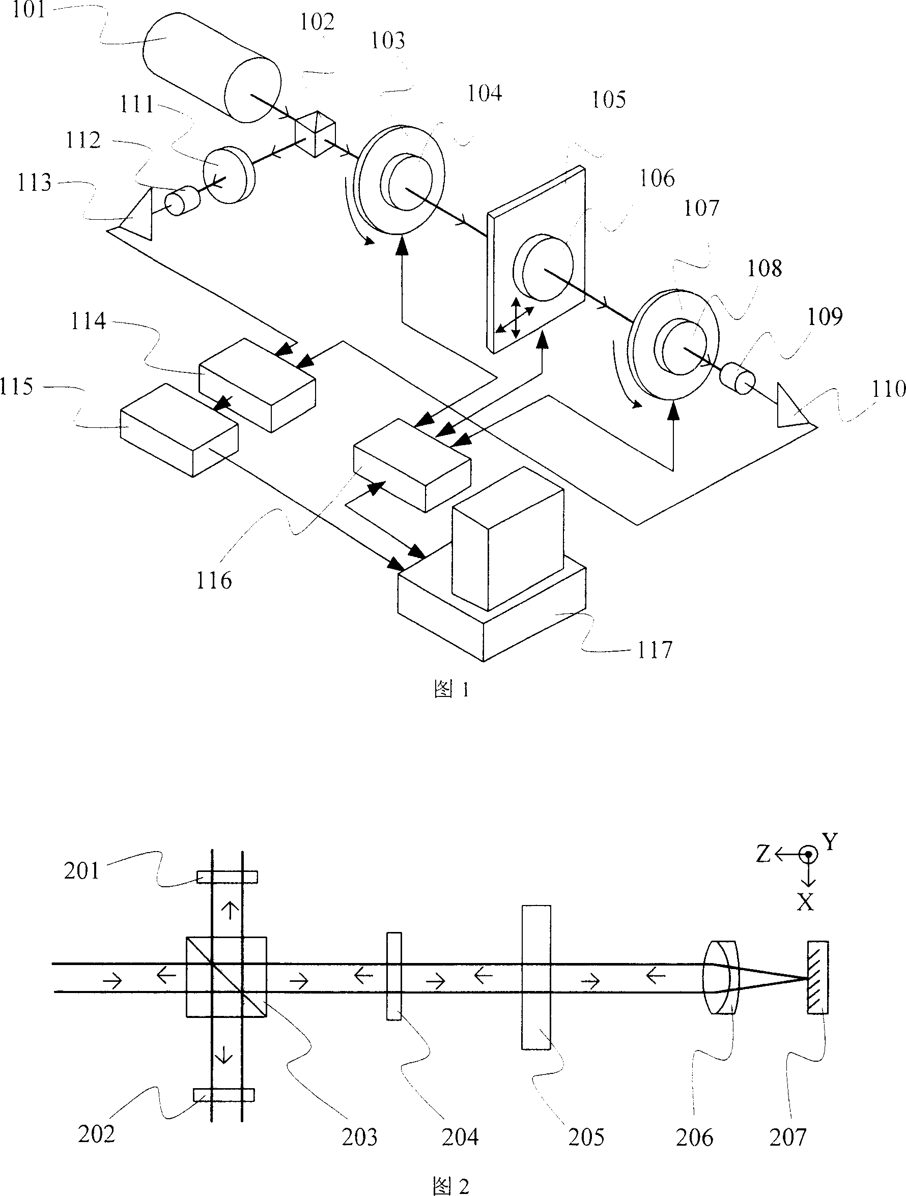
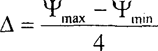
[0041] Measuring method principle of the present invention as shown in Figure 2, 203 is beam splitter, 201 and 202 are polarizers, 204 is 1 / 2 wave plate, 205 is measured sample, 206 is converging lens, 207 is plane reflector . The beam splitter 203 is a neutral non-polarizing beam splitter. The tested sample 205 has a certain birefringence characteristic, which is characterized by a phase retardation and a fast axis direction, the magnitude of the phase retardation is denoted as Δ, and the angle between the fast axis direction and the X axis is denoted as θ. The angle between the fast axis direction of the half-wave plate 204 and the X-axis is denoted as . The incident light contains frequencies f 1 and f 2 The two linearly polarized components of , whose directions are parallel to the X-axis and Y-axis, respectively.

[0042] The orthogonal dual-frequency laser emitted by the laser is used as incident light and is divided into reflected light and transmitted light by the...

Embodiment 2

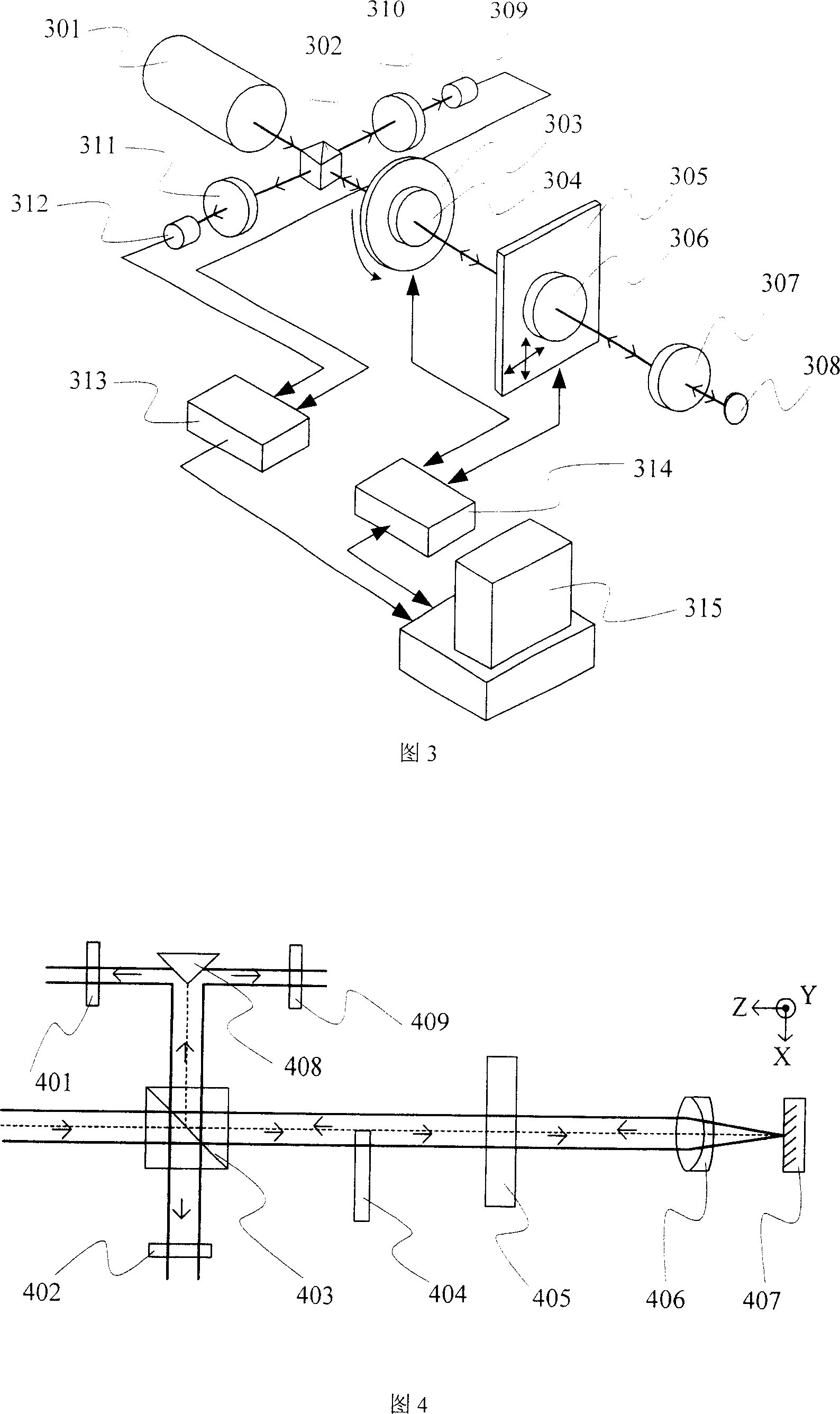
[0053] Fig. 3 has shown the structural schematic diagram of the measuring device that adopts the method embodiment 1 of the present invention, comprises: dual-frequency laser light source 301, spectroscope 302, rotating table 303, the half-wave plate 304 that is arranged on rotating table 303, two A three-dimensional translation stage 305, a measured sample 306, a converging lens 307 and a plane mirror 308, a reference analyzer 311 and a reference photodetector 312, a measurement analyzer 310 and a measurement photodetector respectively arranged on both sides of the beam splitter 302 309, a phase measurer 313 connected with two photodetectors, a controller 314 connected with the rotating platform and a translation platform, and a computer 315 connected with the phase measurer and the controller.

[0054] In the dual-frequency laser light source, the emitted light contains two orthogonal linearly polarized light components of different frequencies, and the frequency difference b...

Embodiment 3

[0070]See Figure 4, which is another embodiment of the method of the present invention. Compared with Embodiment 1, the difference is that the half-wave plate 404 is partly located in the optical path, and this embodiment is partly placed behind the beam splitter 403 and is Before measuring the sample 405, its effect is equivalent to changing the polarization angle of half of the beam of light, while the other half remains unchanged; adding a wedge-shaped reflector, the beam returned from the beam splitter 403 is divided into two halves, respectively and unchanged; two analyzers 401, 409 are respectively placed in the beam separated by the wedge mirror 408. After the two half-beams of light pass through the polarizers 401 and 409 respectively, they are received to form two measurement beat frequency signals, which are compared with the reference beat frequency signals synthesized by the polarizer 402 to obtain two phase differences. This calculates the amount of phase delay an...


PUM

PropertyMeasurementUnit
Corneraaaaaaaaaa

Abstract

The present invention relates to a measurement method and a device for the phase delay quantity and the fast axle direction of a birefringent optical device, which can well solve the problem of poor measurement accuracy in a measurement process. The method is that a pair of orthogonal dual-frequency lasers emitted from an optical laser is divided into reflected light and transmitted light; in a reflected light path and a transmitted light path, through the birefringence of a measured sample measuring point after the polarizing angle of at least one path is changed, and then through the measured sample measuring point after returning, the phases of the polarized components of the two frequencies in the light beams are delayed differently, thus leading to the phase change; then after being synthesized by an analyzer, the two light paths are respectively transformed into a reference beat frequency signal and a measurement beat frequency signal with different phase differences; at least two times of phase differences are obtained, and then the phase delay quantity and the fast axle direction of the measured point can be calculated; the method and the device of the present invention make the measurement of two parameters become simple and eliminate the principle error and the system error.

Description

technical field [0001] The invention belongs to the technical field of laser precision measurement, and in particular relates to the application of laser to measure the phase delay and fast axis direction of birefringent optical devices. Background technique [0002] The birefringence parameters of birefringent optical devices are important indicators to measure their performance, including phase retardation and its fast axis direction, which can be applied in residual stress detection of optical materials, photoelasticity measurement, phase retardation measurement of wave plates, materials And liquid crystal characteristics detection and many other aspects. [0003] At present, the existing detection methods include the quarter-wave plate method and the dual-frequency laser interferometry method. "Test method for edge stress birefringence of colorless optical glass GB7962.6-87" is based on quarter-wave plate measurement, using white light source, manual operation, visual r...

Claims


Application Information

Patent Timeline
IPC IPC(8): G01M11/02
Inventor 蒋弘吴健陈强华柳忠尧李睿颖
Owner 北京市普锐科创科技有限责任公司
Why Eureka
Try Eureka