Continuous heat-storage type fume residual heat recovering device

A recovery device and flue gas waste heat technology, which is applied to the types of heat exchangers, indirect heat exchangers, lighting and heating equipment, etc., can solve the problems of high cost and maintenance costs, waste of fuel and energy, and easy wear and tear of the reversing system , to achieve the effect of convenient engineering management, long device life and compact device structure

Inactive Publication Date: 2008-02-13
UNIV OF SCI & TECH BEIJING
View PDF0 Cites 19 Cited by
  • Summary
  • Abstract
  • Description
  • Claims
  • Application Information

AI Technical Summary

Problems solved by technology

[0006] The purpose of the present invention is to solve the periodic discontinuous operation of regenerator technology, periodic switching of flue gas heat release and air (coal gas) heat absorption process, resulting in fluctuations in furnace pressure, temperature, etc., and volume effects during reversing. Waste of energy, short service life of the heat storage body in a rapidly cooling and rapidly heating environment, complex system, high cost and maintenance cost, large power consumption, easy wear and tear of the reversing system, and short service life

Method used


Image

  • Continuous heat-storage type fume residual heat recovering device
  • Continuous heat-storage type fume residual heat recovering device

Examples


Embodiment 1

[0029] Embodiment 1 (wrong reverse flow)

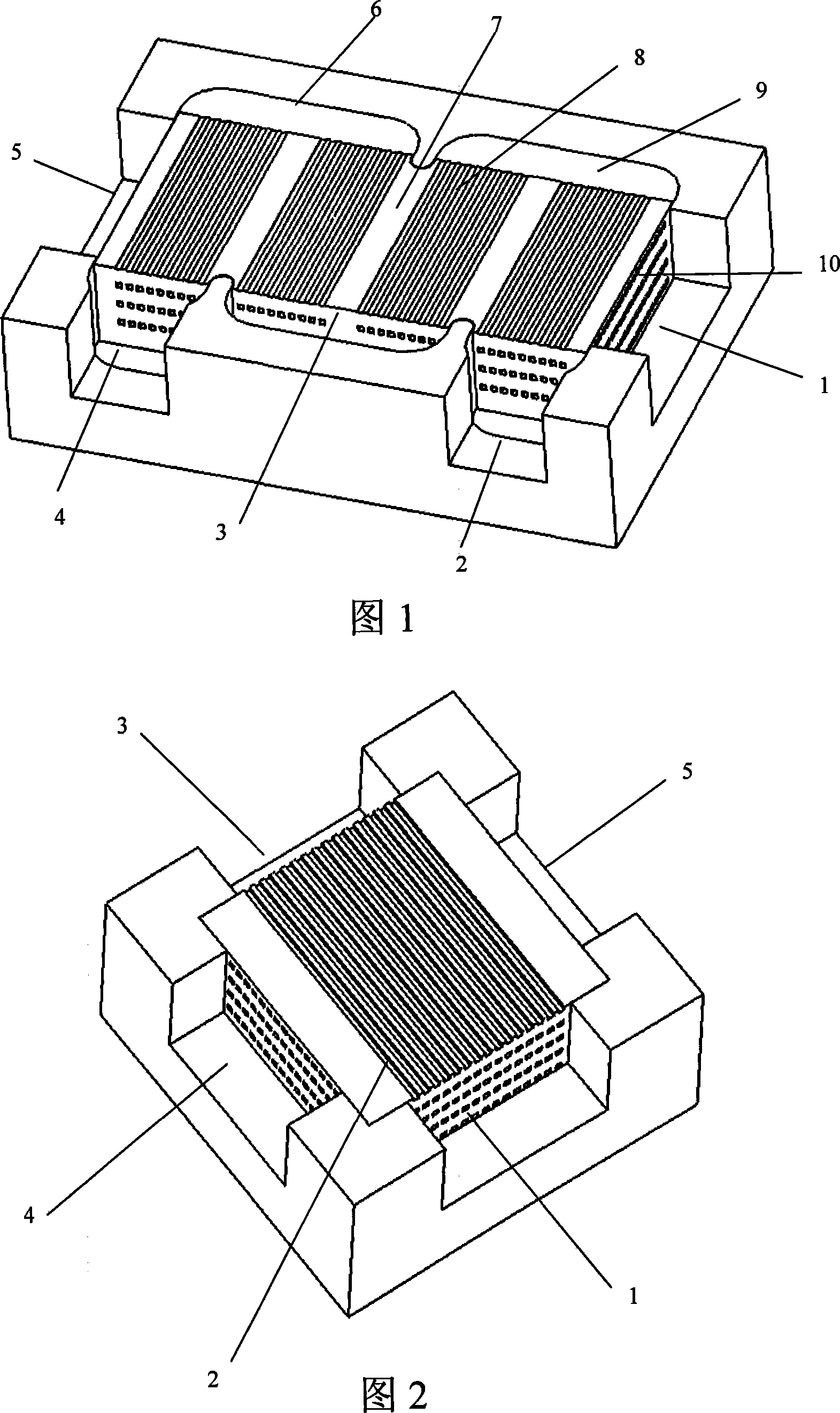
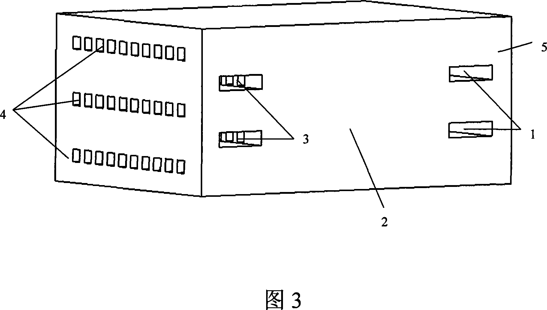
[0030] The continuous regenerative flue gas waste heat recovery device is made of silicon carbide and is directly installed in the flue. After the flue gas enters through the inlet 1, it is evenly distributed to the flue gas channels 10 of each layer, and is directly discharged from the flue gas outlet 5 after passing through the heat storage body 7; after the same air (coal gas) enters through the inlet 4, it is evenly distributed to each layer of air ( In the gas) channel, it enters the gas collecting box 6 after passing through the regenerator vertically, and then turns back and reciprocates through the gas collecting boxes 7 and 9, and then is discharged from the air (gas) outlet 2; the heat in the flue gas is transferred to the The heat storage body, because the thermal resistance of the heat storage body made of high thermal conductivity material is very small, it will quickly conduct heat to the side of the air (gas) channel, a...

Embodiment 2

[0032] Embodiment 2 (vertical cross flow)

[0033] This continuous heat storage flue gas waste heat recovery device is made of silicon nitride material and is directly installed in the flue. The gas outlet 3 is discharged; after the same air (gas) enters from the inlet 4, it is evenly divided into the air (gas) channels of each layer, and is discharged from the air (gas) outlet 5 after passing through the regenerator; the heat in the flue gas is exchanged by convection. The heat is transferred to the heat storage body, and the heat storage body transfers the heat to the side of the air (gas) channel through heat conduction, and then the heat storage body transfers the heat to the cold air (gas) through convective heat exchange to complete the heat recovery process.

Embodiment 3

[0034] Example 3 (countercurrent)

[0035] This continuous heat storage flue gas waste heat recovery device is made of silicon nitride material and is directly installed in the flue. The gas outlet 3 is discharged; after the same air (gas) enters from the inlet 4, it is evenly divided into the air (gas) channels of each layer, and is discharged from the air (gas) outlet 5 after passing through the regenerator; the heat in the flue gas is exchanged by convection. The heat is transferred to the heat storage body, and the heat storage body transfers the heat to the side of the air (gas) channel through heat conduction, and then the heat storage body transfers the heat to the cold air (gas) through convective heat exchange to complete the heat recovery process.


PUM


Abstract

A continuous regenerative flue gas residual heat recycle device belongs to the industrial furnace energy saving field. The device is made from high heat resistance and conduction materials. A gas passage in the device is separated into mutually independent multistory spaces. Flue gas passages and air (gas) passages are arranged in a stratified and staggered way (that is a layer of flue gas passage is connected with a layer of air (gas) passage in the height direction, a staggered arranged sandwich structure). Every layer of gas flow passage is a honeycomb channel, which is made from high thermal conductivity materials. The hest recycle device has the advantages mentioned below. First, the heat exchange rate is fast. The thermal conductivity rate of a regenerator is high. And heat exchange between flue gas and air can be done rapidly. Second, the device can work continuously. Communication is not required in the wind supply and the smoke exhaust. And the system is simple. Third, utmost waste recovery is really realized. No heat and fuel loss caused by volume effect is made during the communication. Fourth, with a long service life, the device can be flexibly arranged. And the device has relative small relevance with the furnace, which makes the failure risk lowered and is convenient for the engineering management.

Description

Technical field: [0001] The invention belongs to the field of energy saving of industrial furnaces and kilns, and relates to waste heat recovery technology and devices in high-temperature industrial furnaces, in particular to a technology and a device capable of recovering waste heat of flue gas in a continuous regenerative manner. technical background: [0002] The waste heat of flue gas in industrial furnaces accounts for a large part of the total heat. The key to saving energy and reducing consumption is to recover and make good use of the waste heat of flue gas. At present, the flue gas waste heat recovery technology used in industrial furnaces mainly includes heat exchangers and regenerators. However, both of these two technologies have shortcomings, which restrict their application and development. [0003] For the heat exchanger, its disadvantages mainly include: (1) The heat exchanger has high requirements on the temperature resistance and corrosion resistance of th...

Claims


Application Information

Patent Timeline
Patent Type & Authority Applications(China)
IPC IPC(8): F28D9/02
Inventor 夏德宏郑克明张世强敖雯青薛根山
Owner UNIV OF SCI & TECH BEIJING
Why Eureka
Try Eureka