

Bionic underwater chelonian robot
A technology of underwater robots and bionic sea turtles, which is applied to underwater ships, underwater operating equipment, motor vehicles, etc., can solve problems such as inability to realize heave motion, non-adjustability, etc., and achieve autonomous navigation, small size Lightweight, noise reduction effect
- Summary
- Abstract
- Description
- Claims
- Application Information
AI Technical Summary
Problems solved by technology
Method used
Image

Examples
Embodiment 1
[0022] Embodiment 1: (Some dotted boxes in the drawings can be marked and described as a component, and explain that there are many ways to solve these components or units in the prior art, otherwise it may be considered insufficient disclosure. )
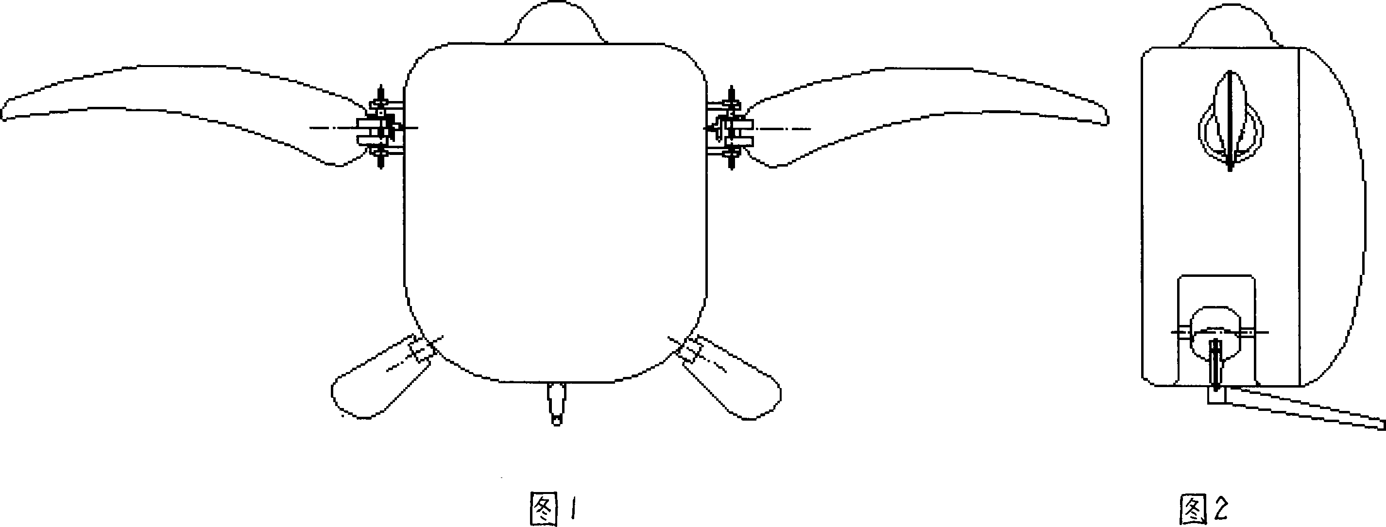
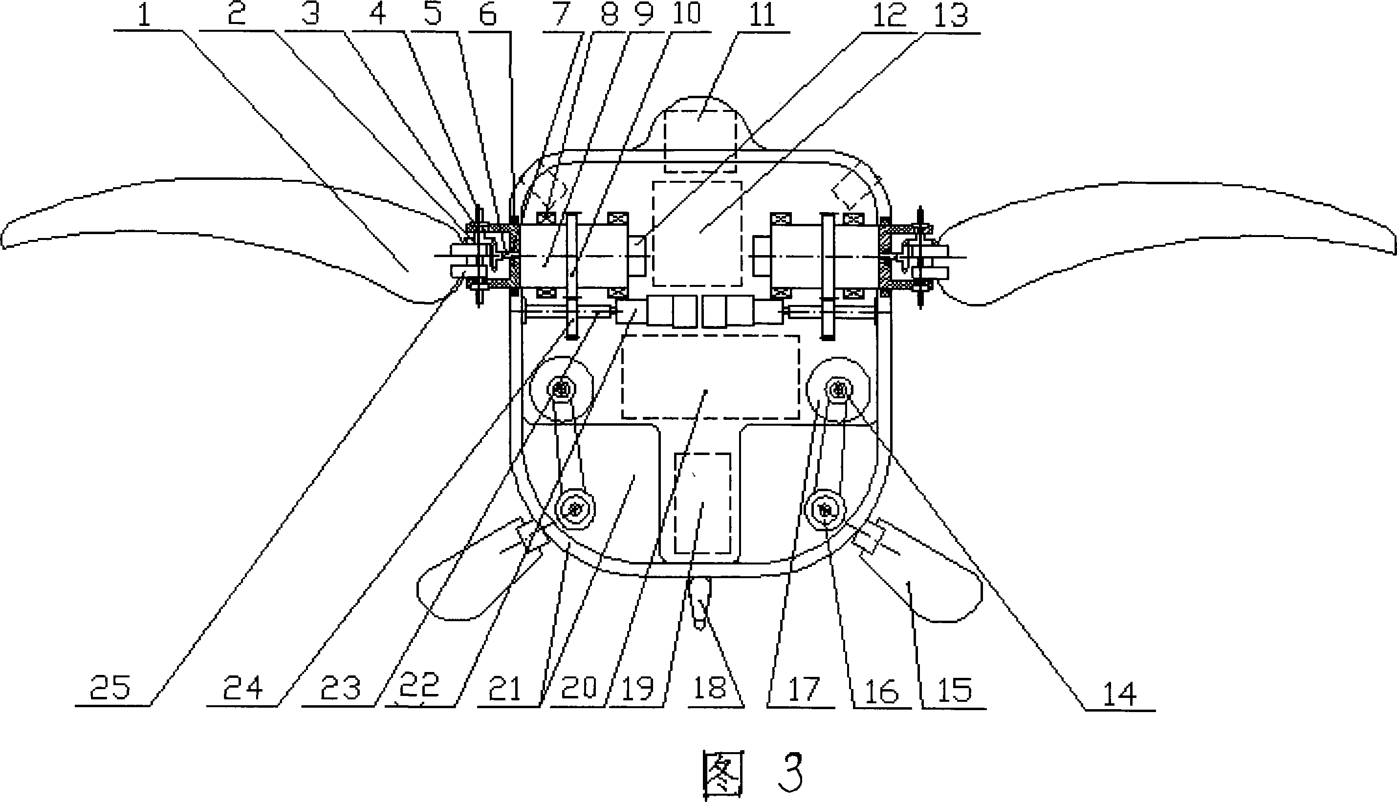
[0023] With reference to Figures 1-5, this embodiment includes a turtle-shaped streamlined shell, a sensing and testing unit installed on the front head and shoulders of the turtle-shaped streamlined shell, a control drive unit in the front chest, a power storage unit in the lower abdomen, and a communication unit at the rear and tail. The system unit, the forelimb movement unit and the hindlimb movement unit, the sensor test unit consists of sonar detectors, underwater cameras, and multi-beam light sources, the control drive unit consists of executive level and coordination level controllers, and the power reserve unit includes motor drives The power supply module and the controller power supply module, the communication system un...
Embodiment 2
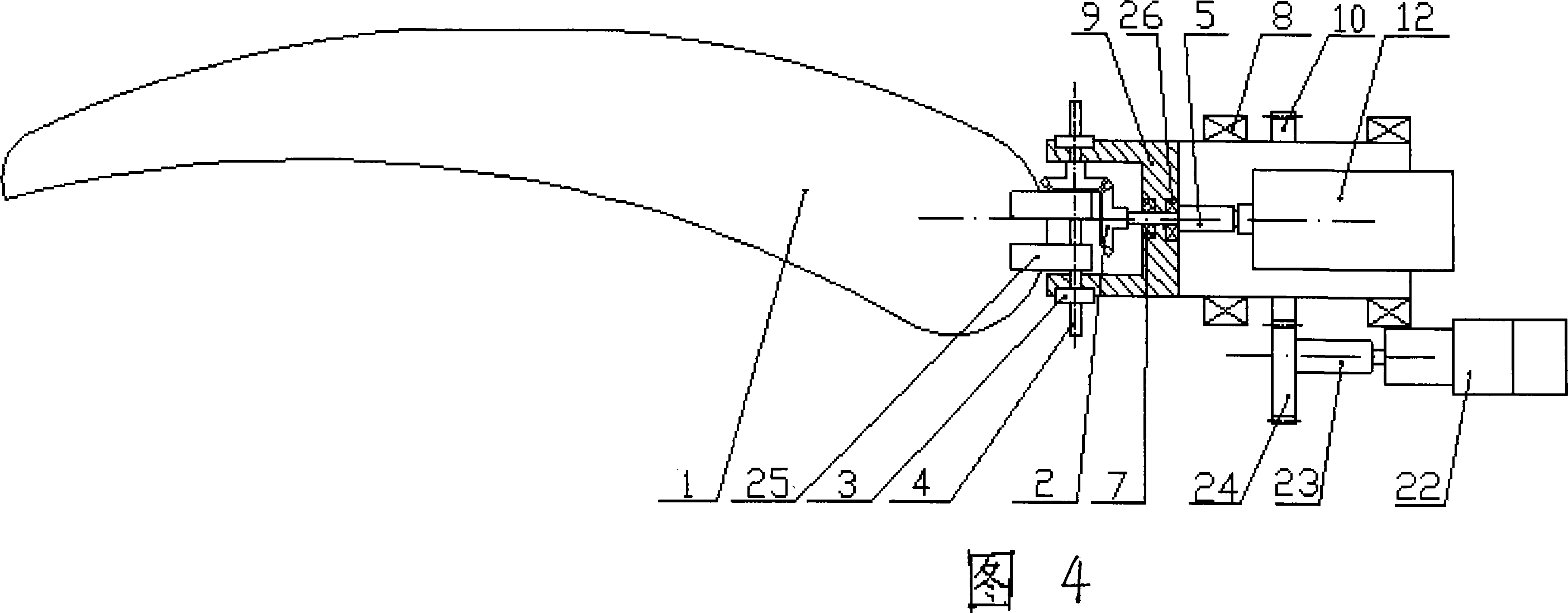
[0032] Combined with Fig. 3, Fig. 4 and Fig. 5, the basic structure of the bionic sea turtle robot in this embodiment is the same as in Embodiment 1, and the heave motion is converted on the basis of horizontal linear motion. and the hind limbs maintain a gliding state at a certain deflection angle. Taking the robot’s upward swimming as an example, the implementation plan of the asymmetrical hydrofoil swimming method of the forelimb is: according to the operation sequence of the motors in the hydrofoil method mentioned in the previous paragraph, when the front edge of the forelimb plate 1 sinks and flaps to the rear lower end, Motor 22 continues to start clockwise, rotates 180 ° and forelimb board 1 is forwarded to the front upper end of its motion. Motor 12 starts then, and still carries out slapping water backward and downward, and omits the upward and backward slapping of water of forelimb, and this is equivalent to an asymmetrical hydrofoil method swimming cycle. The foll...
Embodiment 3
[0034]With reference to Fig. 3, Fig. 4 and Fig. 5, the basic structure of the bionic sea turtle robot of this embodiment is the same as that of Embodiment 1, and the turning motion is also converted on the basis of horizontal linear motion. Continue hydrofoil swimming, and the hind limbs act as steering rudders; while when a small turning radius is required, the forelimbs perform single-limb hydrofoil swimming, and the hind limbs act as steering rudders. The hydrofoil method swimming of forelimb sees above; And the steering rudder effect of hindlimb, take the right hindlimb as example, its specific implementation scheme is: take the gliding state when advancing in a straight line as the initial position, when needs to turn right, the motor 41 stop after clockwise rotation 90 °, make hind limb board 15 transfer to vertical state from horizontal state. Then motor 17 starts counterclockwise, makes hind limb board 15 turn rightwards from the rearmost end, and the angle of rotation...
PUM
 Abstract
Description
Claims
Application Information