Optical false proof nondestructive testing apparatus

A non-destructive testing and optical anti-counterfeiting technology, applied in the field of applied optics, can solve the problems of complex anti-counterfeiting label production process, high production cost, sample damage, etc., and achieve the effect of improving operation safety, service life and efficiency

Inactive Publication Date: 2008-03-12
CHANGCHUN INST OF OPTICS FINE MECHANICS & PHYSICS CHINESE ACAD OF SCI
View PDF0 Cites 3 Cited by
  • Summary
  • Abstract
  • Description
  • Claims
  • Application Information

AI Technical Summary

Problems solved by technology

[0004] In order to solve the problems of damage to samples caused by the detection process in the background technology, complex anti-counterfeiting label production process, and high production cost, the present invention provides an optical anti-counterfeiting non-destructive testing device

Method used


Image

  • Optical false proof nondestructive testing apparatus
  • Optical false proof nondestructive testing apparatus

Examples


Embodiment 1

[0028] Switch 1 is a light touch electronic switch with a spring, the model is KFC-A03-04.

[0029] The battery 2 is a 3V lithium battery.

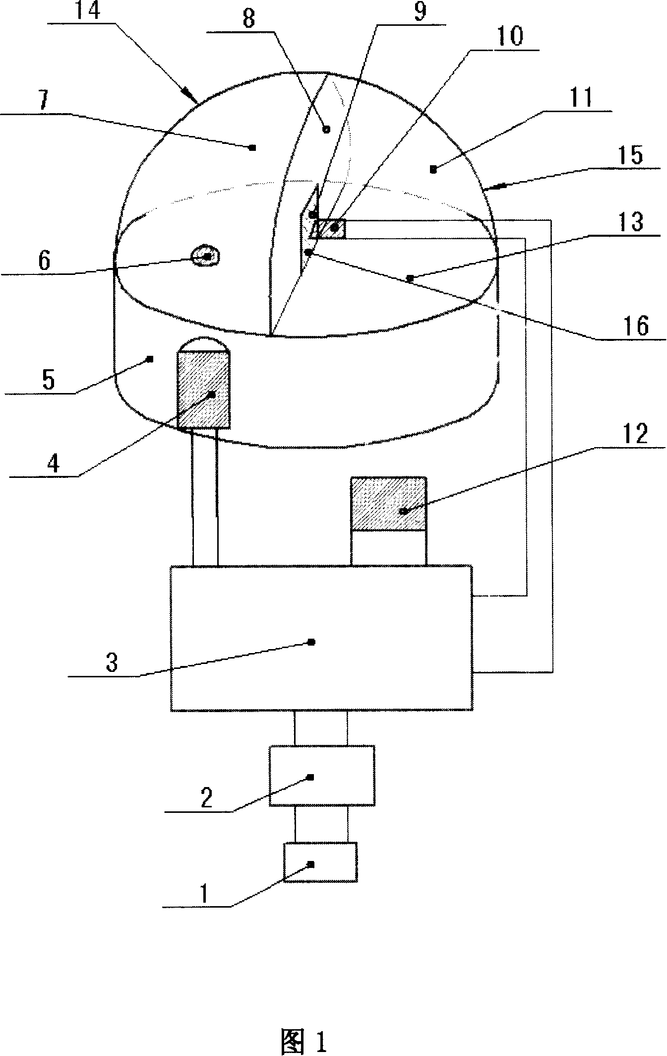
[0030] The electronic circuit board 3 is an electronic circuit board with six pins, the positive and negative poles of the exciting light source 4 are connected to the a and b pins respectively, the positive and negative poles of the photodetector 10 are connected to the c and d pins respectively, and the output device 12 The positive and negative poles are connected to the e and f pins respectively, as shown in Figure 1.

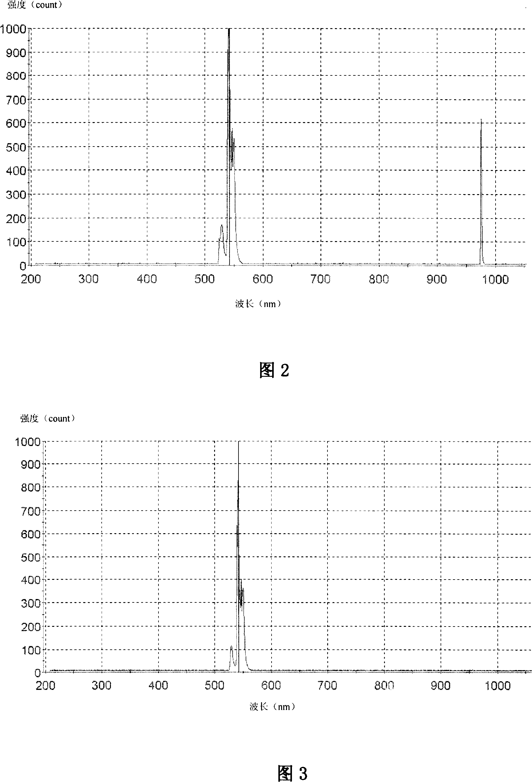
[0031] The excitation light source 4 is a semiconductor laser (LD). At a room temperature of 20° C., the central wavelength of the emitted laser light is 980 nm, and the bandwidth of the emitted laser peak is 1 nm-3 nm. The power is 200mW.

[0032] Exciting light source bracket 5 is a circular plate structure with a certain thickness made of red copper material. There is a through hole on the left side of the circula...

Embodiment 2

[0043] The only difference between this embodiment and Embodiment 1 is: the excitation light source 4 adopts a light-emitting diode (LED), and the central wavelength of its emitted light is the same as the absorption wavelength of the infrared (up-conversion) fluorescent material, which is 980nm, and the bandwidth of the emitted laser peak 5nm-10nm.

Embodiment 3

[0045] The difference between this embodiment and embodiment 1 is:

[0046] The excitation light source 4 is a semiconductor laser (LD). At a room temperature of 20° C., the central wavelength of the emitted laser is 973 nm, the bandwidth of the emitted laser peak is 1 nm-3 nm, and the power is 200 mW. The halide material system doped with rare earth elements uses europium (Eu 3+ ) Yttrium (Yb 3+ ) co-doped silicate, after absorbing infrared light with a wavelength of 973nm, the emitted fluorescence characteristic line is visible orange light with a wavelength of 593nm.

[0047] The reflective film on the inner cavity wall of the left sub-chamber cover 14 has high reflectivity to the 973nm near-infrared light emitted by the excitation light source 4, and has high reflectivity to the 593nm visible fluorescence emitted by the infrared (up-conversion) fluorescent material.

[0048] The reflective film on the inner cavity wall of the right sub-chamber cover 15 has a high reflect...


PUM


Abstract

The invention belongs to the field of optical application; the invention is an optical fraud-proof non-destruction device with an optical method for commodities labeled with infrared fluorescent material. The invention comprises a switch, a battery, an electronic circuit board, a laser source, a laser source support, a dark chamber, a chamber partition wall, an optical filter device, a photoelectric detector and an output device. The switch, the battery and the electronic circuit board inside the invention is connected into a circuit in series; the positive and negative electrodes of the laser source are linked to the electronic circuit board; the laser source is arranged on the laser source support. The optical filter device is positioned at a light hole on the chamber partition wall; the photoelectric detector is arranged in the right chamber; the positive and negative electrodes of the photoelectric detector are connected with the electronic circuit board; the positive and negative electrodes of the output device are linked to the electronic circuit board. The invention is characterized by safe operation, long service life and high efficiency of the laser source, sensitive receiving with the photoelectric detector, low fabrication cost and etc, so as to really fulfill fraud-proof and non-destruction.

Description

technical field [0001] The invention relates to the field of applied optics, in particular to a device for anti-counterfeiting and non-destructive detection of commodities with infrared (up-conversion) fluorescent materials as anti-counterfeiting marks by using an optical method. Background technique [0002] Today, with the rapid development of the commodity economy, the anti-counterfeiting detection of commodities has become an important issue related to the interests of consumers. Non-destructive testing is a new technology that emerged with the development of high technology. This technology is different from traditional chemical analysis methods, does not damage the sample, and ensures the integrity of the sample while obtaining sample information. The anti-counterfeiting detection of biological seeds and daily consumer goods requires no damage to the samples, and it is easy for professional technicians to make accurate judgments on the spot. Therefore, an optical anti-...

Claims


Application Information

Patent Timeline
Patent Type & Authority Applications(China)
IPC IPC(8): G06K7/10G01N21/64
Inventor 郑权赵岭贾富强
Owner CHANGCHUN INST OF OPTICS FINE MECHANICS & PHYSICS CHINESE ACAD OF SCI
Why Eureka
Try Eureka