
Rotary drying machine

A dryer and central tube technology, applied in the field of dryers, can solve the problems of reduced contact area between materials and hot air, short circuit of flue gas, uneven wind speed, etc., achieve reasonable distribution of resistance and wind speed, increase evaporation speed and Intensity, the effect of changing the state of material movement

Inactive Publication Date: 2008-03-19
南京旋立重型机械有限公司
View PDF0 Cites 60 Cited by
  • Summary
  • Abstract
  • Description
  • Claims
  • Application Information

AI Technical Summary

Problems solved by technology

The working state of the traditional rotary dryer is shown in Figure 2. Due to the unreasonable form, geometric shape and layout of the L-shaped lifting plate, the material can only be scattered in the first quadrant, which leads to uneven material spreading in the section of the cylinder. No "material curtain" can be formed. In the two areas of A and B, "wind tunnel" and "ladder" type material columns are prone to appear, resulting in poor material dispersion, reduced contact area between materials and hot air, low heat transfer efficiency, and material Problems such as difficulty in controlling the water content of the machine
Due to the uneven distribution of the lifting plate in the inner circumference of the dryer, there are cavities, and the heat is discharged through the cavities without sufficient contact with the materials, resulting in a decrease in the thermal efficiency of the dryer.
According to some data, the time that the material particles stay in the air in the traditional dryer is only 10-12.5% ​​of the time when they sink in the cylinder and the lifting plate.
At the same time, during the rotation process of the dryer, the L-shaped lifting plate has a low lifting height and a small throwing range.
The axial flow rate is fast, and the section of the cylinder cannot be used to the maximum extent. A large amount of hot air escapes from the center of the dryer, and an obvious short circuit phenomenon of flue gas is formed on the larger section of the cylinder. This is the traditional dryer. root cause of inefficiency
Figure 3 is a schematic diagram of the wind speed inside the cylinder of a traditional rotary dryer. It can be seen from the figure that the wind speed inside the cylinder is uneven, the wind speed in the middle is high, hot air is easy to escape from the middle, and the drying efficiency is low.

Method used


Image

  • Rotary drying machine
  • Rotary drying machine
  • Rotary drying machine

Examples


Embodiment 1

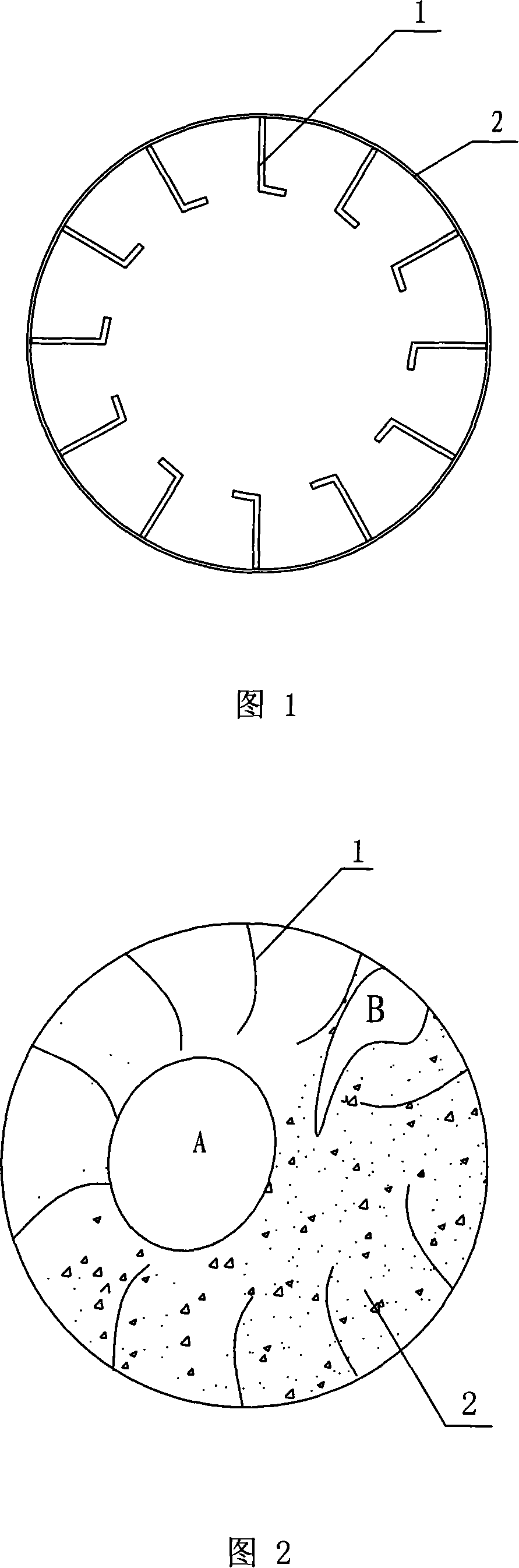
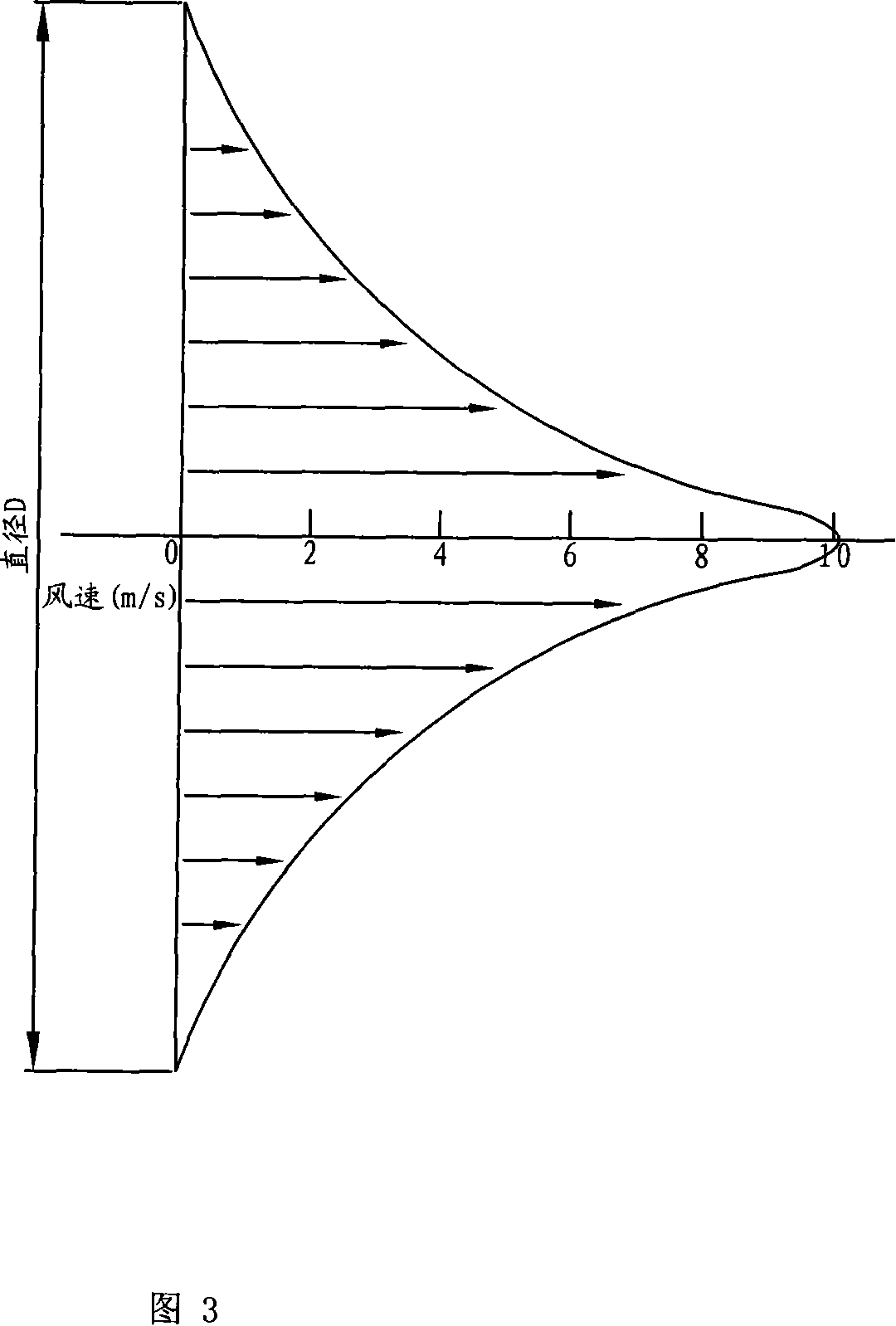
[0027] In this embodiment, a traditional rotary dryer with a diameter of 2.4×18m and an hourly output of 12-13t / h is technically transformed. A central tube is arranged in the center of the cylinder, and an X-shaped lift is arranged on the central tube. sheet. The four lifting veneers of the X-type lifting plate have the same shape and are evenly distributed on the outer circumference of the central tube. One end of the four lifting veneers is welded to the central tube, and the other end is bent upward at 135 degrees. The center pipe is fixedly supported on the cylinder body through the support rod, which is used to support the center pipe. The support rods are channel steel, and there are four, which are evenly distributed on the outer circumference of the central tube, and are located between the lifting veneers of the X-shaped lifting plates. One end of the support rod is welded to the outer wall of the central tube. In order to prevent the thermal expansion of the centra...


PUM


Abstract

The invention relates to a drying machine, which is a rotary drying machine, and comprises a barrel body. A lifting blade is arranged in the peripheral direction of the inner wall of the barrel body, a central tube is arranged in the center of the barrel body, and an X-shaped lifting blade is arranged on the central tube. The invention leads the central X-shaped lifting blade to be additionally arranged in the drying machine, the material entering into the drying machine is firstly brought to a certain height through the lifting blade along the peripheral direction, then the material is cast and lifted, the material after being cast enters into the central X-shaped lifting blade, the material is cast again in the X-shaped lifting blade, thereby forming the material casting layer upon layer, because the material in the X-shaped lifting blade is unceasingly cast, the dwell time of the material in the X-shaped lifting blade is prolonged, the exchange chance of the material and the hot air is increased, thereby improving the heat exchange efficiency in the drying machine.

Description

technical field [0001] The invention relates to a dryer, in particular to a rotary dryer. Background technique [0002] Rotary dryer, also known as rotary drum dryer, is used to dry materials within a certain humidity range. It is an important equipment for clean production in building materials, metallurgy, electric power, mining and other industries. Rotary dryers are mainly used in cement plants to dry clay, limestone, coal, sand, quartz, blast furnace slag, etc.; they can also be used in industrial sectors such as metal ore dressing plants, steel plants, chemicals, and fertilizers without chemical changes. Materials that produce toxic and harmful gases. The moisture content of the dried material can be lower than 1%. The humidity entering the dryer should not be bonded to the cylinder and the lifting plate, and the temperature of the gas entering the dryer is generally controlled below 700°C. As the mainstream drying equipment in the current market, the rotary dryer i...

Claims


Application Information

Patent Timeline
IPC IPC(8): F26B11/06
Inventor 王志强
Owner 南京旋立重型机械有限公司
Features
  • Generate Ideas
  • Intellectual Property
  • Life Sciences
  • Materials
  • Tech Scout
  • Unparalleled Data Quality
  • Higher Quality Content
  • 60% Fewer Hallucinations
Learn More