Bridgeless boost converter with PFC circuit

A boost converter, positive feedback technology, applied in the conversion equipment of intermediate conversion to DC conversion, irreversible AC power input conversion to DC power output and other directions, can solve the problem of energy management circuit complexity, such as the increase of engineers and manufacturers , to achieve the effect of good efficiency, reduced requirements and small effective area

Inactive Publication Date: 2008-03-26
INTERNATIONAL RECTIFIER COEP
View PDF1 Cites 22 Cited by
  • Summary
  • Abstract
  • Description
  • Claims
  • Application Information

AI Technical Summary

Problems solved by technology

Additionally, there is a voltage drop associated with the current sense resistor R
[0025] Increased comp

Method used


Image

  • Bridgeless boost converter with PFC circuit
  • Bridgeless boost converter with PFC circuit
  • Bridgeless boost converter with PFC circuit

Examples


Example Embodiment

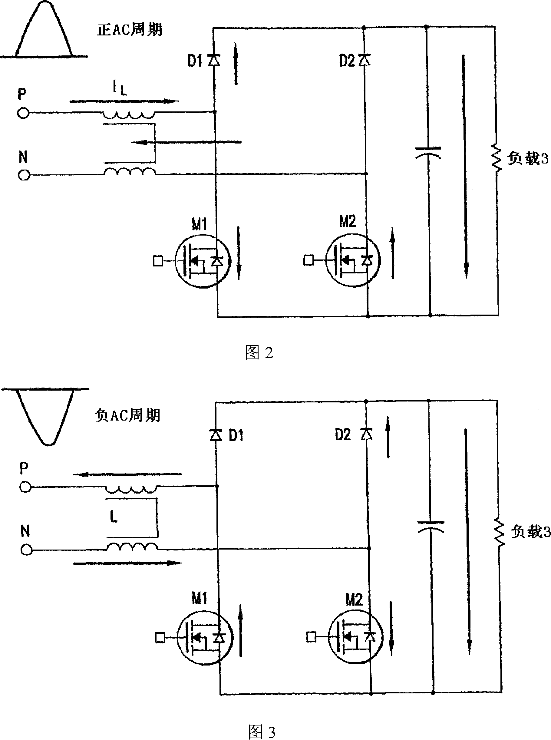
[0059] The circuit of FIG. 5 places the inductor in the AC circuit before the rectifier diodes D1-D4, so that D1 and D3 have dual functions of rectifier and boost diodes. It is obvious that the improved circuit has a smaller diode drop in power flow. Since the circuit runs at 120Hz, switching losses are virtually eliminated, and D1-D4 and Q1-Q2 are standard speed components, which have the added benefit of lower conduction losses than fast semiconductors. Q1 and Q2 may be, for example, IGBTs.

[0060] The controller senses the zero-voltage interleaving of the AC input signal and generates PWM drive signals for IGBTs Q1 and Q2.

[0061] The circuit delivers a power factor greater than 0.99 without current induction with characteristic line variations exceeding + / - 10%. Efficiency > >98% delivering 1KW in a 230VAC circuit at a DC bus voltage of 280V.

[0062] The IGBT switches can be small (crystal area #2) because they only turn on for half the cycle of the turn even if driv...


PUM


Abstract

A boost type power supply circuit for providing a DC output voltage comprising first and second semiconductor switches coupled between respective input lines and a common connection; an AC input voltage from an AC source being supplied across the input lines; first and second diodes coupled in series with respective ones of the switches; third and fourth diodes coupled across respective ones of the switches in a free-wheeling relationship with the switches; an inductance coupled in at least one of the input lines; a controller for controlling the conduction times of the switches by providing a pulse width control signal to each of the switches; wherein the controller turns on at least one of the switches during a positive half cycle of the AC voltage to allow energy storage in the inductance and turns off the at least one switch to allow the energy stored in the inductance to be supplied to an attached load through one of the first and second diodes and one of the third or fourth diodes; and the controller turns on at least one of the switches during a negative half cycle of the AC voltage to allow energy storage in the inductance and turns off at least one switch to allow the energy stored in the inductance to be supplied to the attached load through one of the first and second diodes and one of the third and fourth diodes. The controller determines an on-time and an off-time of a pulse of the pulse width modulated control signal during each half cycle of the AC voltage, the on-time and off-time of the pulse being controlled to regulate said output voltage and to provide power factor correction of said AC input voltage, based on either voltage sensing or current sensing.

Description

[0001] related application [0002] This application is based on and claims priority from US Provisional Patent Application Serial No. 60 / 666,950 (IR-2965PROV), filed March 31, 2005, which is hereby incorporated by reference. [0003] This application is a continuation-in-part (IR-2593) of U.S. Application Serial No. 10 / 953,344, filed September 29, 2004, which is hereby incorporated by reference, based on Serial No. 60, filed October 1, 2003 U.S. Provisional Patent Application No. / 507,901 and claiming priority therefrom, is hereby incorporated by reference. technical field [0004] The present invention relates to a bridgeless boost converter with PFC (Positive Feedback Circuit), and more particularly to a converter circuit such as can be applied in air conditioners. Background technique [0005] In all industrialized and emerging countries, the increased demand for indoor air conditioning systems driven by environmental changes has begun to affect summer energy consumption...

Claims


Application Information

Patent Timeline
IPC IPC(8): H02M7/04H02M5/42
Inventor P·伍德
Owner INTERNATIONAL RECTIFIER COEP
Why Eureka
Try Eureka