Optical film

A technology of optical film and optical surface, which is applied in the field of optical film and can solve problems such as poor wear resistance

Inactive Publication Date: 2008-04-16
ETERNAL MATERIALS CO LTD
View PDF3 Cites 12 Cited by
  • Summary
  • Abstract
  • Description
  • Claims
  • Application Information

AI Technical Summary

Problems solved by technology

Although China Taiwan Patent No. M291542 discloses an optical modulation component that simultaneously achieves the purpose of light collection and light uniformity by including an arc-shaped columnar structure (ie, a diffuser) and a prism columnar structure (ie, a light-collection section), but, As mentioned above, because of its prism columnar structure, it is easy to contact with other diaphragms or panels to cause scratches, so the wear resistance is not good

Method used


Image

  • Optical film
  • Optical film
  • Optical film

Examples


preparation example 1

[0065] The preparation of preparation example 1 resin formula A

[0066] Take a 250 ml glass bottle, and add solvent: 40 grams of toluene into the glass bottle. Add acrylate monomers sequentially under high-speed stirring: 10 grams of dipentaerythritol hexaacrylate, 2 grams of trimethylolpropane triacrylate, 14 grams of pentaerythritol triacrylate, oligomer: 28 grams of aliphatic aminomethyl Ester hexaacrylate [Etercure 6145-100, Eternal Company], photoinitiator: 6 grams of 1-hydroxycyclohexyl phenyl ketone, and finally foamed into a resin formula A with a solid content of about 60% and a total weight of about 100 grams.

preparation example 2

[0067] Preparation Example 2 Mold Roller Engraving

[0068] The surface of the precision roller is electroplated with electroless nickel or oxygen-free copper, using a CNC precision lathe and a single crystal diamond cutter, the lathe speed is below 500rpm, the upper limit of the feed is 0.015 mm, and the numerical control (NC) program is written according to the set pattern Process and prepare the desired microstructure grooves on the surface of the roller as a mold for subsequent processing.

Embodiment 1

[0070] Preparation of microstructure layer

[0071] 60 g of EM210  (2-phenoxyethyl acrylate, sold by Eternal Company) and 60 grams of 624-100  (epoxy acrylate, sold by Eternal Company) mixes, then adds 5 grams of Chivacure  BP was used as a photoinitiator (benzophenone, provided by Double Bond Chemicals) and stirred at 50° C. and a rotation speed of 1,000 rpm to form a colloidal coating composition.

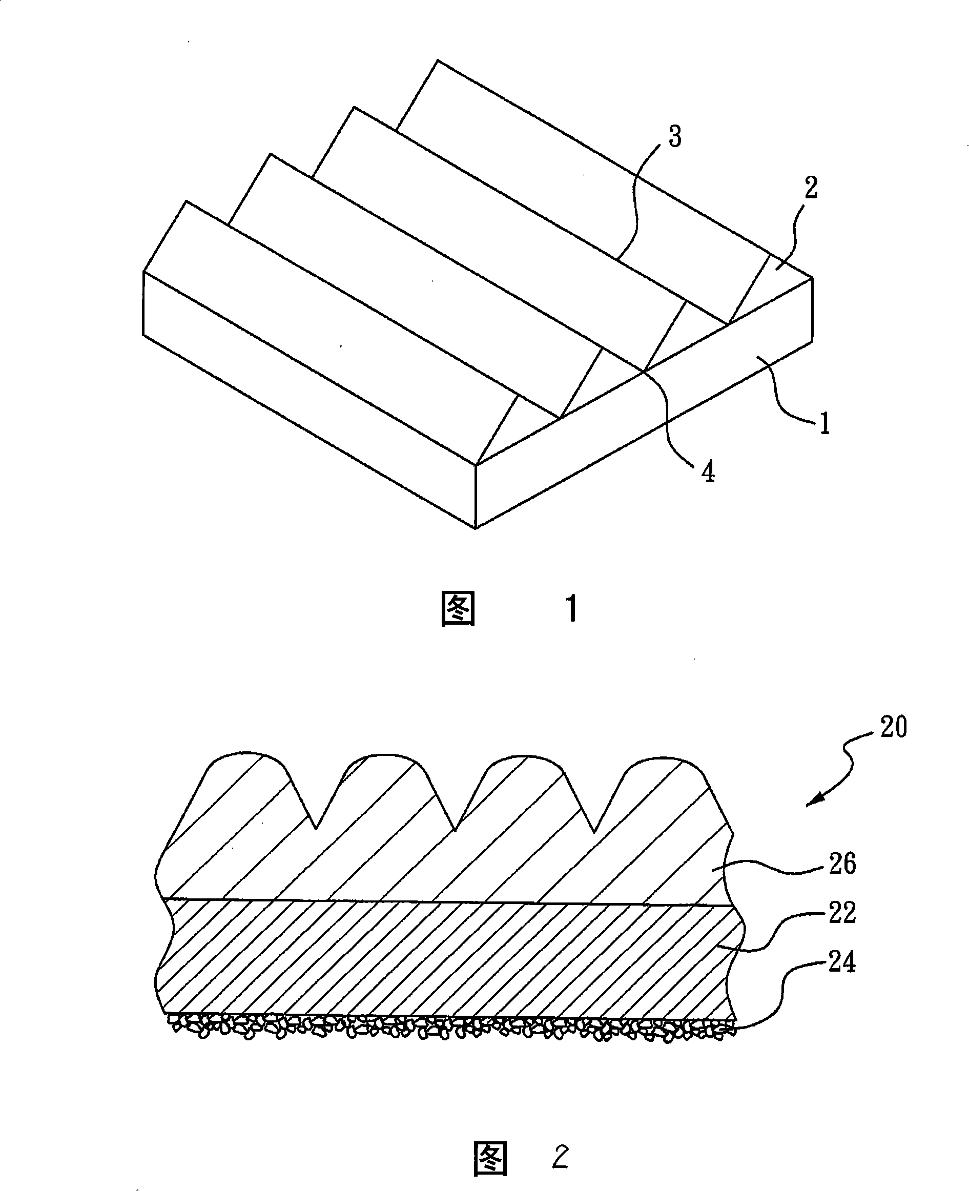
[0072] This colloidal coating composition is coated on a polyethylene phthalate (PET) substrate (U34  , produced by TORAY Company) to form a coating, and then use the roller with microstructure grooves obtained in Preparation Example 2 to form a structured surface on the coating in an embossing manner. Then, at room temperature, with energy rays (200-400nm UV lamp, intensity: 150-300mJ / cm 2 , time: 2 to 15 seconds) to irradiate the coating to cure it. 10 is an image of the microstructure layer of the optical film of Example 1 produced by a scanning electron microscope (...


PUM

PropertyMeasurementUnit
heightaaaaaaaaaa
particle diameteraaaaaaaaaa

Abstract

The invention provides an opticalal film, comprising base material with a first optical face and a second optical face, and a microstructure layer arranged at the surface of the base material; the microstructure layer comprises a plurality of free prismati column structures, taper structures, solid angle structures, orange petal block structures, a first light-adjusting structure combined by the prism column structures, taper structures, solid angle structures, orange petal block structures; and the microstructure layer also comprises a plurality of free arc column structures, lens structures, capsule structures and a second light-adjusting structure combined by the arc column structures, lens structures, capsule structures; wherein, the height of at least one part of the second light-adjusting structure is larger than the height of the whole first light-adjusting structure. The optical film of the invention can avoid the damage of the microstructure layer and also has the light-gathering effect; meanwhile, the optical film can effectively reduce optical interference.

Description

technical field [0001] The invention relates to an optical film, especially a light-gathering film applied to a liquid crystal display. Background technique [0002] Conventionally, a backlight module used for a liquid crystal display mainly uses a diffusion plate, a diffusion film, and a light concentrating film to achieve light uniformity and light collection. The main function of the diffusion plate and the diffusion film is to provide a uniform surface light source for the liquid crystal display. Concentrating film is commonly known as Brightness Enhancement Film or prism film in the industry. The main function of concentrating film is to collect scattered light through refraction and internal total reflection, and concentrate it to a positive angle of about ±35 degrees. Viewing angle (On-axis) direction, in order to improve the brightness of LCD. Generally, the commonly used light-condensing film system uses regularly or irregularly arranged linear prism columnar stru...

Claims


Application Information

Patent Timeline
Patent Type & Authority Applications(China)
IPC IPC(8): G02B5/04G02B1/10G02B5/126G02B5/12G02B6/00G02F1/1335G02B1/14G02B1/16
Inventor 吴定原汪宗兴汪乙嘉
Owner ETERNAL MATERIALS CO LTD
Why Eureka
Try Eureka