Technique for continuously smelting copper by employing oxygen bottom converter and device thereof

An oxygen bottom blowing and process technology, applied in the direction of improving process efficiency, can solve problems such as low-altitude pollution, and achieve the effect of reducing load and high smelting direct yield

Active Publication Date: 2008-04-23
CHINA ENFI ENGINEERING CORPORATION
View PDF0 Cites 72 Cited by
  • Summary
  • Abstract
  • Description
  • Claims
  • Application Information

AI Technical Summary

Problems solved by technology

[0010] The technical problem to be solved by the present invention is to overcome the shortcomings of the prior art, and provide an effective method to solve the problem of low-altitude SO in copper smelting PS converter blowing. 2 pollution problems, while providing a more advanced, shorter process,

Method used


Image

  • Technique for continuously smelting copper by employing oxygen bottom converter and device thereof
  • Technique for continuously smelting copper by employing oxygen bottom converter and device thereof

Examples


Embodiment 1

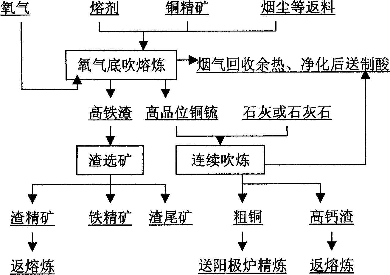
[0078] A technique for continuous copper smelting by oxygen bottom blowing is characterized in that the technique comprises the following steps:

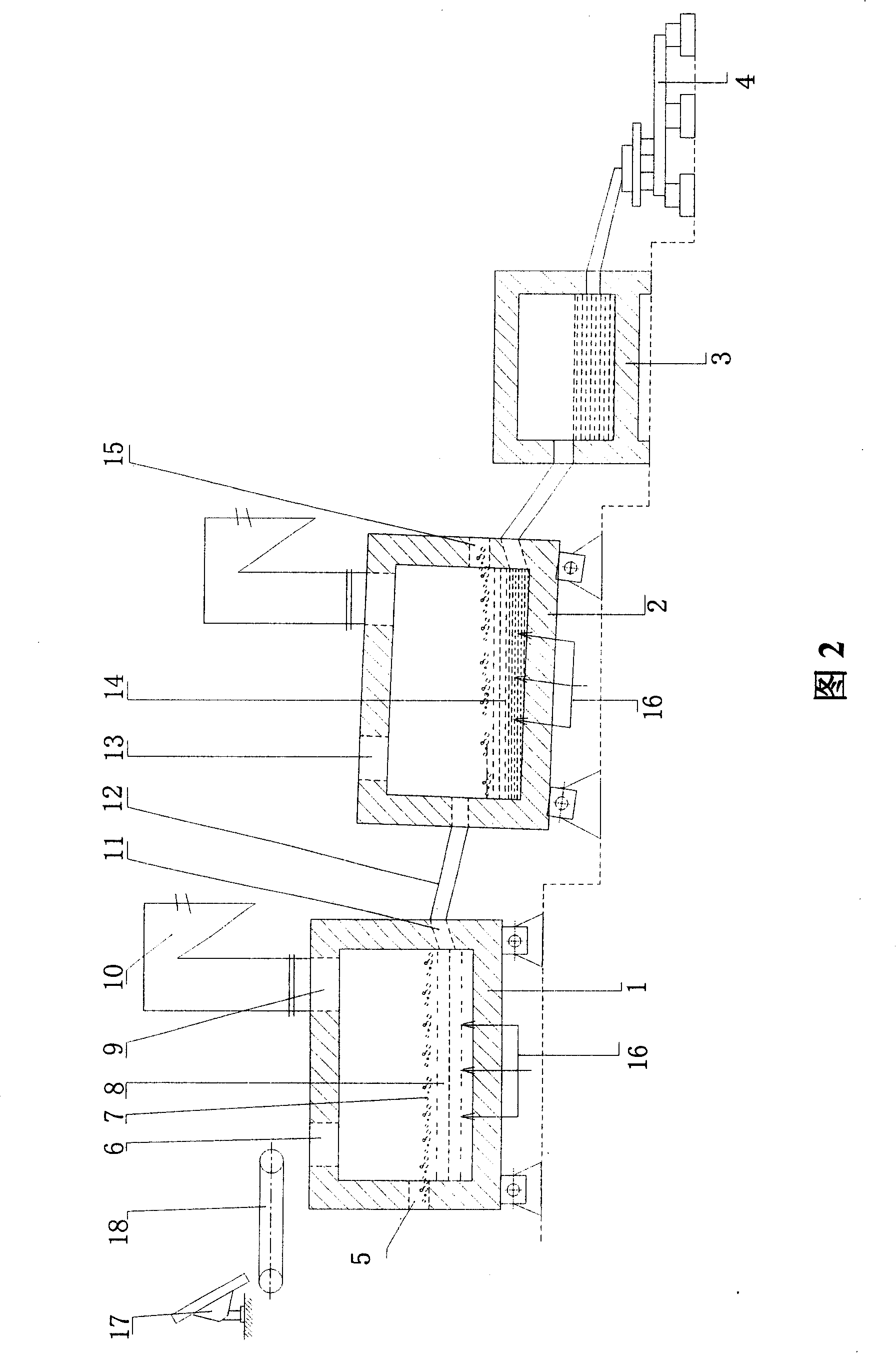
[0079] (1) Copper sulfide concentrate and flux, returned intermediate copper materials including dust, slag copper concentrate, blowing furnace slag, etc., are mixed and granulated by a disc granulator, and sent to the bottom blowing smelting furnace by a belt feeder The upper part of the furnace feed port is fed into the furnace, and oxygen is sent into the furnace through the oxygen spray gun installed at the bottom of the furnace at an angle of 0° to the vertical line for smelting reaction. The temperature is 1080°C;

[0080] (2) The copper matte generated by the bottom-blowing smelting furnace is discharged to the chute connected with the bottom-blowing smelting furnace through the siphon discharge port at one end of the bottom-blowing smelting furnace; the copper matte is sent to the end of the bottom-blowing smelting furnace t...

Embodiment 2

[0086] Oxygen is fed into the furnace through the oxygen lance installed at the bottom of the furnace at an angle of 16° to the vertical for smelting reaction, and oxygen is fed through the oxygen lance installed at the bottom of the bottom blowing furnace at an angle of 16° to the vertical for blowing The mixed pellets are smelted to produce copper matte and smelting slag. The melting temperature is 1100°C and the blowing temperature is 1250°C. Except for the high-temperature flue gas, the others are the same as those described in Example 1.

Embodiment 3

[0088] A process for continuous copper smelting using oxygen bottom blowing, characterized in that:

[0089] Copper matte converting refers to: the liquid high-temperature copper matte produced from the bottom-blown smelting furnace is continuously injected into the bottom-blown converting furnace with oxygen through the chute, and oxygen-enriched air is continuously fed from the bottom of the converting furnace to continuously blow high-grade copper matte ;

[0090] At the same time, the furnace top is not opened, and the flux lime powder is sent into the furnace with oxygen through the silo and metering belt feeder according to the calculation requirements to make slag from the oxygen lance; One end has a hole at the upper part to discharge smelting slag, and a hole at the lower part to set up a siphon device to discharge blister copper to realize continuous addition of copper matte, continuous blowing, continuous addition of flux, continuous slagging, continuous slag discha...


PUM

PropertyMeasurementUnit
Thicknessaaaaaaaaaa

Abstract

The present invention relates to continuous copper-smelting oxygen bottom blowing furnace process and apparatus. The continuous copper-smelting process includes smelting high grade copper matte in an oxygen bottom blowing furnace, smelting coarse copper product with the high grade copper matte in one other bottom blowing furnace, producing high iron slag, dressing the furnace slag to obtain copper concentrate and returning to smelting furnace, separating out iron concentrate product and obtaining tailings. The process has short flow path, low investment, low power consumption, low cost, environment friendship and other advantages.

Description

technical field [0001] The present invention relates to a non-ferrous metal smelting copper smelting method and its device, more specifically to a continuous copper smelting process and device using an oxygen bottom blowing furnace. Background technique [0002] As far as smelting is concerned, the pyrometallurgy of copper in my country has been used in industrial production: flash furnace smelting, Noranda smelting, Osmelt smelting, Aisa smelting, autothermal smelting, silver smelting and traditional blast furnace Melting, electric furnace melting, reverberatory furnace melting, etc. The above smelting methods are relatively advanced smelting processes adopted in the world today, except for the latter three traditional methods which are difficult to meet the emission standards required for environmental protection. As far as copper blowing is concerned, more than 90% of the world today use PS converters, which operate intermittently, and the copper matte produced by smeltin...

Claims


Application Information

Patent Timeline
IPC IPC(8): C22B15/00C22B5/00C22B9/00
CPCY02P10/20
Inventor 蒋继穆尉克俭张振民史学谦林晓芳
Owner CHINA ENFI ENGINEERING CORPORATION
Why Eureka
Try Eureka