Eureka AIR delivers breakthrough ideas for toughest innovation challenges, trusted by R&D personnel around the world.

Nuclear grade platinum resistance thermometer and its method for reducing thermal response time

A platinum resistance thermometer technology, applied in the field of temperature measurement instruments, can solve the problems of long thermal response time, large thermal inertia, poor thermal conductivity of MgO powder, etc. of platinum resistance thermometers, and achieve the effect of reducing thermal response time and improving thermal conductivity

Inactive Publication Date: 2008-05-07
NO 3 AUTOMATION INSTR & METERS FACTORY SHANGHAI AUTOMATION INSTR & METERS CO LTD
View PDF0 Cites 10 Cited by
  • Summary
  • Abstract
  • Description
  • Claims
  • Application Information

AI Technical Summary

Problems solved by technology

The conventional platinum resistance thermometer encapsulates the ceramic platinum resistance element in a metal protective sleeve, and the platinum resistance element is filled with MgO powder for insulation and shock resistance. Contact, MgO powder itself has poor thermal conductivity, and in order for the platinum resistance thermometer to withstand long-term high temperature, high pressure, radiation and high-speed coolant impact, it is necessary to add an external protective tube. These two factors make the thermal response time of the platinum resistance thermometer relatively slow. Long (greater thermal inertia), τ 0.632 ≥8s, obviously, conventional platinum resistance thermometers cannot meet the needs of the nuclear power industry

Method used


Image

  • Nuclear grade platinum resistance thermometer and its method for reducing thermal response time
  • Nuclear grade platinum resistance thermometer and its method for reducing thermal response time

Examples


Embodiment Construction

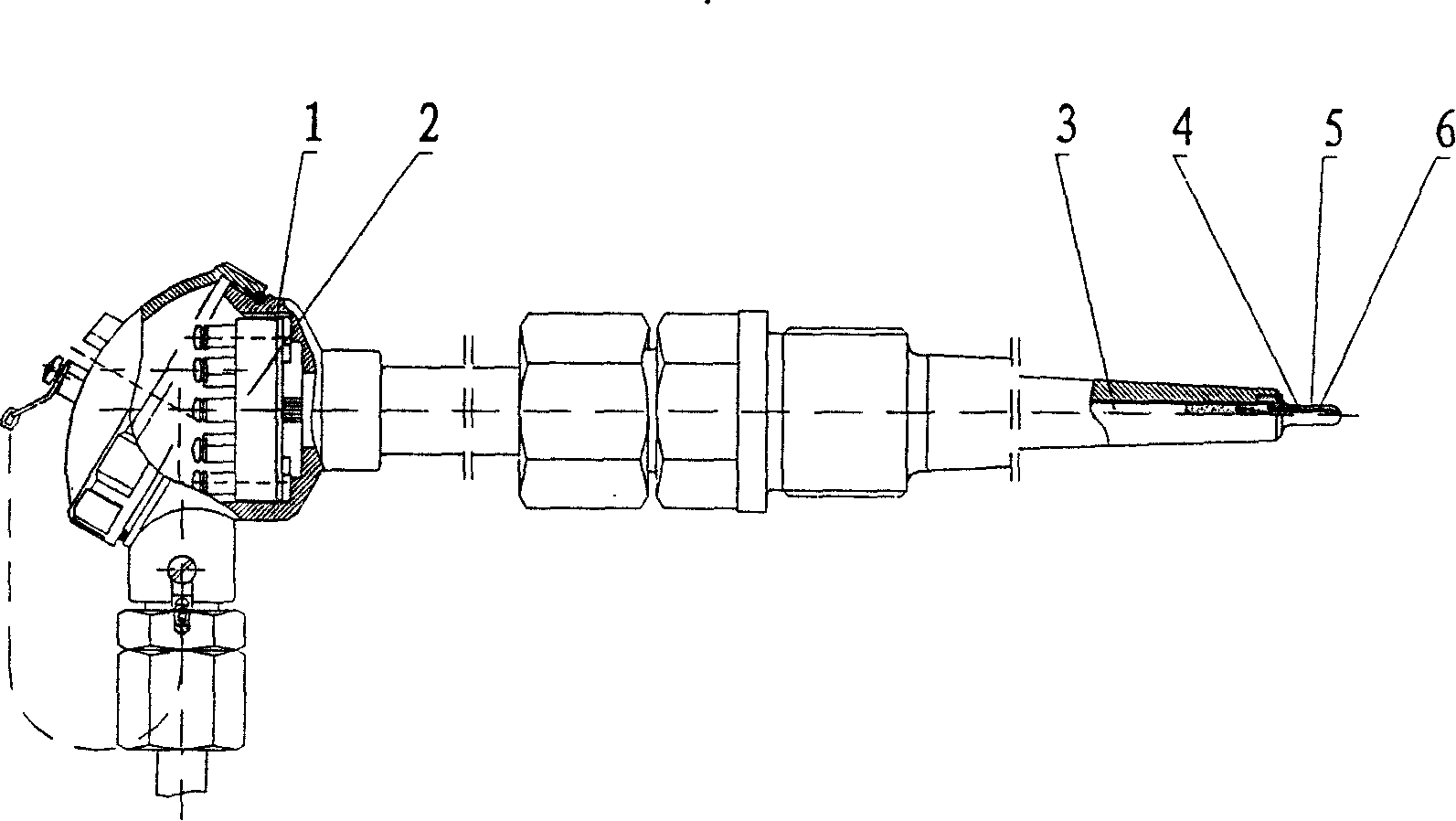
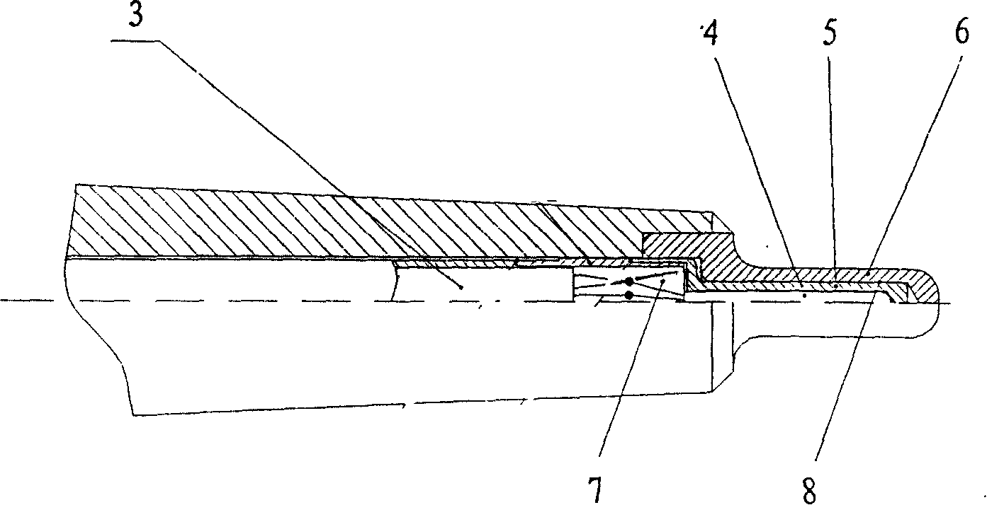
[0014] The nuclear-grade small inert platinum resistance thermometer includes: a junction box 1, a wiring wrench 2 placed in the junction box, and a protective sleeve 5 with a built-in platinum resistance element 4, which is characterized in that: the temperature sensing surface of the platinum resistance element 4 is connected to the protective The inner surface of the casing 5 is closely attached; the outer surface of the protective sleeve 5 is closely attached to the inner surface of the outer protective tube 6; the platinum resistance element 4 is welded to the armored lead wire 3, and the lead wire is filled with MgO powder 7 .

[0015] The gap between the platinum resistance element 4 and the inner surface of the protective sleeve 5 is 0.10 mm. The gap between the outer surface of the protective sleeve 5 and the inner surface of the outer protective tube 6 is 0.05 mm. The outer surface of the protective sleeve 5 is coated with a wear-resistant, heat-resistant and oxidat...


PUM

PropertyMeasurementUnit
porosityaaaaaaaaaa

Abstract

The invention relates to a nuclear-grade platinum resistance thermometer and the method for reducing thermal response time with the invention, comprising a terminal box, a wiring board arranged in the terminal box, and a protective sleeve with a built-in platinum resistance element, wherein, the temperature sensing surface of the platinum resistance element is clung tightly to the inner surface of the protective sleeve, and no MgO powder is filled between the platinum resistance element and the protective sleeve; the outer surface of the protective sleeve is clung tightly to the inner surface of an external protective tube; the platinum resistance element is welded with an armored leading wire; MgO powder is filled in the armored leading wire; a metal coat is plated on the outer surface of the protective sleeve. The invention has the advantages that due to the temperature sensing surface of the platinum resistance element clung tightly to the protective sleeve and the protective sleeve clung tightly to the external protective tube, the heat conductivity of the thermometer is improved; the thermal response time is reduced; the earthquake resistant requirement for nuclear power station is satisfied; due to wear-resistant, heat-resistant, and oxidation-resistant special metal coating on the surface of the protecting sleeve, the protecting sleeve does not stick to the protective tube due to oxidation corrosion.

Description

technical field [0001] The invention belongs to the technical field of temperature measuring instruments, and in particular relates to a method for improving the structure of a platinum resistance thermometer and reducing the thermal response time, so that it is suitable for nuclear power plants and provides coolant for reactor power control systems, reactor protection systems and thermal control systems. temperature signal. Background technique [0002] The working conditions of nuclear power plants are extremely harsh. In the reactor cooling system, small inert platinum resistance thermometers for measuring the temperature of the cold and hot sections of the loop and the average temperature are nuclear safety level 1 equipment, and the instruments are required to withstand long-term high temperature, high pressure, radiation and The working condition of high-speed impact of the coolant, and it must be able to withstand the test of a considerable intensity of earthquakes. A...

Claims


Application Information

Patent Timeline
Patent Type & Authority Applications(China)
IPC IPC(8): G01K7/18G01K1/16G01K1/08G01K1/12
Inventor 宋平杨金良贺国良
Owner NO 3 AUTOMATION INSTR & METERS FACTORY SHANGHAI AUTOMATION INSTR & METERS CO LTD
Why Eureka
Eureka Blog
Learn More