
Semi solid rheoforming method for metal parts and device therefor

A semi-solid rheological and metal parts technology, applied in the field of semi-solid metal forming, can solve the problems of high performance requirements of screw materials, difficulty in installing heat preservation devices, and insufficient shear rate, so as to reduce slurry preparation costs, increase service life, The effect of reducing restrictions on the use of materials

Inactive Publication Date: 2008-05-21
HUAZHONG UNIV OF SCI & TECH
View PDF10 Cites 45 Cited by
  • Summary
  • Abstract
  • Description
  • Claims
  • Application Information

AI Technical Summary

Problems solved by technology

The disadvantages are: the material performance requirements of the screw in the equipment are high (satisfying the wear resistance and corrosion resistance at high temperature, etc.); the shear rate usually generated by single screw stirring is not high enough
The disadvantage of this method is that the vibrator inserted into the melt is easily corroded by the metal melt and pollutes the metal melt; when the melt passes through the bottom, the vibration efficiency is reduced due to the absorption of the vibration by the slurry container
Literature Micro-structure evolution of semi-solid Al-7Si-0.4Mg alloy by short time supersonic vibration (Al-7Si-0.4Mg alloy structure evolution of short-time ultrasonic vibration treatment) (Liu C, Pan Y and Aoyama S.In: Proc .of the 5th Int.Conf.on Semi-Solid Processing of Alloys and Composites, Colorado, USA, 1998: 439-447) also provides a kind of ultrasonic vibrating head to indirectly vibrate the melt by acting on the slurry container wall The method of semi-solid slurry, which has the problem of being difficult to install heat preservation devices

Method used


Image

  • Semi solid rheoforming method for metal parts and device therefor
  • Semi solid rheoforming method for metal parts and device therefor
  • Semi solid rheoforming method for metal parts and device therefor

Examples


example 1

[0058] Ultrasonic vibration of ZL101 aluminum alloy was used to prepare semi-solid parts. The liquidus temperature of ZL101 aluminum alloy is 616°C and the solidus temperature is 567°C. The alloy is melted in a resistance furnace and heated to 740°C, refined and degassed for later use. The temperature of the alloy liquid is maintained at about 660°C by means of a temperature control device. Take an appropriate amount of molten aluminum, pour it into a slurry container, use the temperature control system (temperature adjustment device 13 and temperature controller 11) to control the temperature of the melt at 610°C, and the cooling rate of the melt is 0.1-3°C / s.

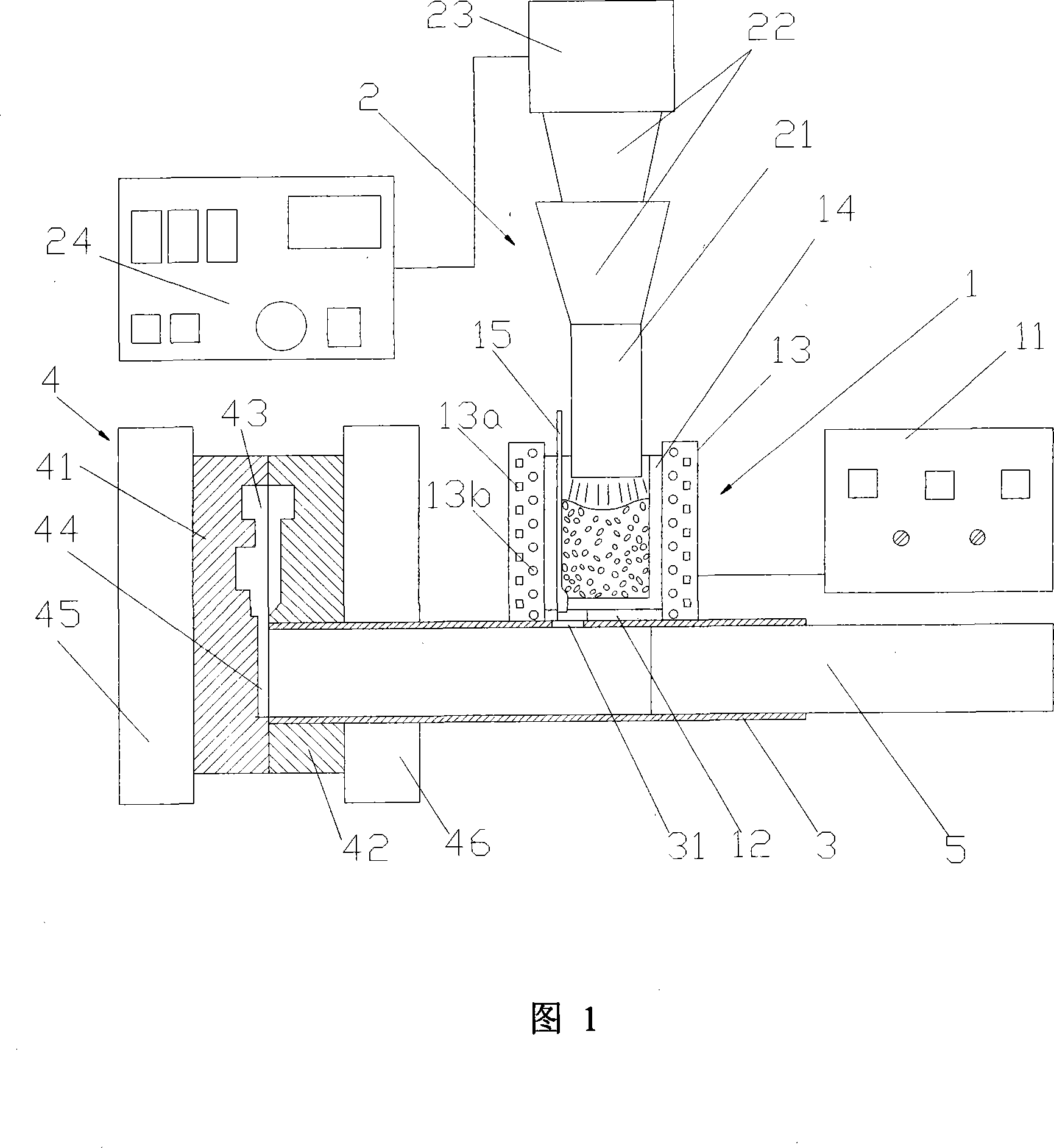
[0059] Move the ultrasonic radiation head 21 to 10 mm above the molten aluminum in the slurry container (FIG. 1), and perform ultrasonic pulse radiation on the melt. The radiation frequency is 20kHz, and the radiation volume power is 30W / cm 3 . The radiation time is 150s. After the ultrasonic treatment is stopped...

example 2

[0062] A390 aluminum alloy was used to prepare semi-solid state by ultrasonic vibration. The liquidus temperature of A390 aluminum alloy is 650°C and the solidus temperature is 505°C. The alloy is melted in a resistance furnace and heated to 770°C, refined and degassed for later use. The temperature of the alloy liquid is kept at about 680°C by means of a temperature control device. Take an appropriate amount of molten aluminum and pour it into a slurry crucible (Figure 1). Use a temperature control device to control the temperature of the alloy liquid at 650°C, and the cooling rate of the melt is 0.1-3°C / s.

[0063] The ultrasonic radiation head 21 was moved to 15 mm above the molten aluminum in the crucible 14 to perform ultrasonic pulse radiation on the melt. Radiation frequency is 25kHz, radiation volume power is 40W / cm 3 . The radiation time is 180s. After the ultrasonic treatment is stopped, the temperature of the semi-solid melt is lowered to 630° C. to 635° C. thr...

example 3

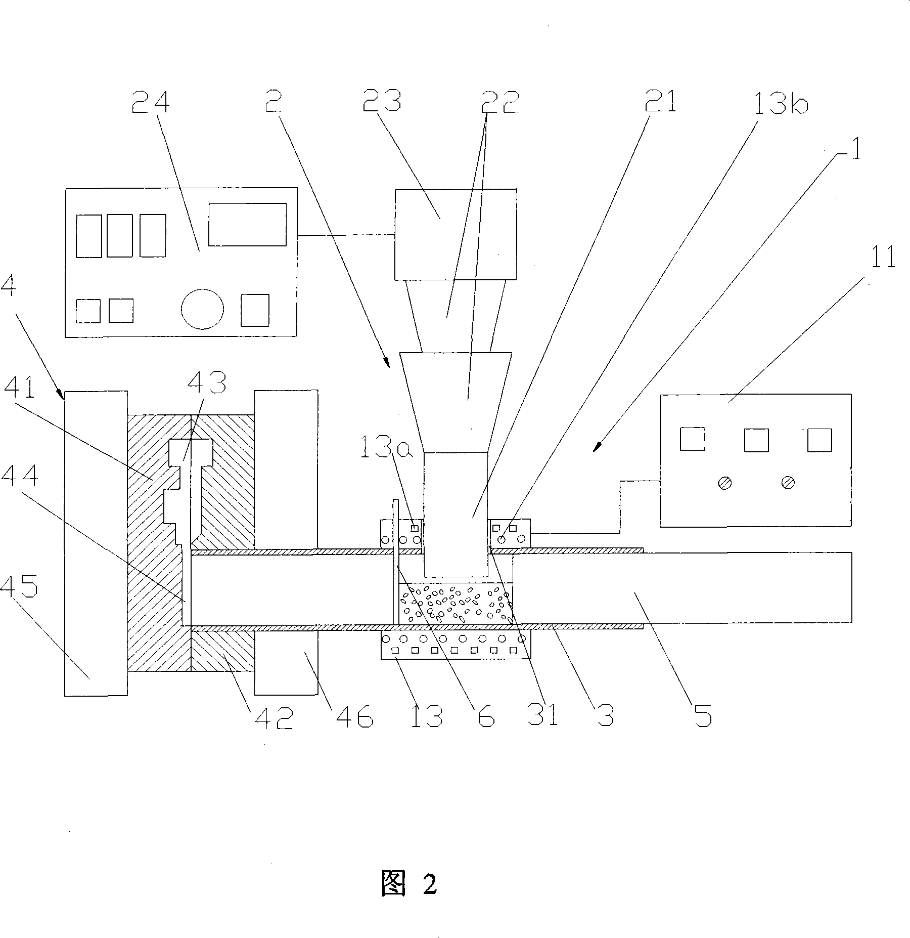
[0066] Ultrasonic vibration of AZ91 magnesium alloy was used to prepare semi-solid state. The liquidus temperature of AZ91 magnesium alloy is 595°C and the solidus temperature is 470°C. The alloy is melted in a resistance furnace and heated to 680°C, refined and degassed for later use. The temperature of the alloy liquid is maintained at about 640°C by means of a temperature control device. Take an appropriate amount of magnesium liquid and pour it into the sleeve 3 (Figure 2). Use the temperature control system to control the temperature of the sleeve and the melt at 590°C, and the cooling rate of the melt is 0.1-3°C / s.

[0067]The ultrasonic radiation head 21 was moved to 10 mm above the molten magnesium in the sleeve 3 to perform ultrasonic pulse radiation on the melt. The radiation frequency is 20kHz, and the radiation volume power is 20W / cm 3 . The radiation time is 100s. After the ultrasonic treatment is stopped, the temperature of the semi-solid melt is lowered to ...


PUM


Abstract

The invention relates to a semi-solid fluidized molding method and a device for metal parts. Liquid metal with the temperature from 0 to 40 DEG C above liquid phase is guided into a pulp container, and then an ultrasonic radiation is lowered down to 1 to 30mm above the liquid surface, ultrasonic radiation is started, and the slurry is cooled at the speed ranging from 0.1 DEG C per second to 3 DEG C per second. The ultrasonic radiation can be pulse radiation or non-radiation pulse with ultrasonic frequency ranging from 12kHz to 80kHz, radiation volume power 5W / cm<3> to 100W / cm<3>, and radiation time from 15s to 1000s; the slurry is poured into molding equipment to be molded into parts after the radiation. The molded part has dense organization, fine and equally distributed grains. The device of the invention comprises a pulp container, a thermostat, an ultrasonic generation and a control unit, a sleeve, and a mold and an injection rod and a molding device. The fluidized molding method and device can be used for fluidized molding of various alloy parts made from aluminum, magnesium, tin, copper and iron etc. The method has the advantages of non-contaminated pulp, long service life of ultrasonic equipment and high part production efficiency.

Description

technical field [0001] The invention belongs to the field of semi-solid metal forming, and in particular relates to a semi-solid rheological forming method and device for metal parts. technical background [0002] The so-called semi-solid metal forming technology is that when the molten metal is cooled to a temperature between the solidus and liquidus, it is vigorously stirred or disturbed, or the thermal state of the metal is changed, or a grain refiner is added. , or carry out rapid solidification, that is, change the nucleation and growth process of the primary solid phase, and obtain a solid-liquid mixed slurry in which a certain spherical primary solid phase is evenly suspended in the liquid metal mother liquid (the solid phase component is generally 50 %, even up to 60%), use this solid-liquid mixed slurry to directly carry out forming processing; or first completely solidify this solid-liquid mixed slurry into a billet, then cut the billet according to needs, and then...

Claims


Application Information

Patent Timeline
Patent Type & Authority Applications(China)
IPC IPC(8): B22D1/00
Inventor 吴树森赵君文毛有武
Owner HUAZHONG UNIV OF SCI & TECH
Learn More