Solar energy heat pipe heat pump device and its implementing method

A technology of solar heat pipe and heat pump device, which is applied to indirect heat exchangers, fluid heaters, machine operation modes, etc., can solve the problems of high installation direction restrictions, single heat source, large power consumption, etc., so as to reduce energy consumption. and defrost time, system reliability, and the effect of improving heat pump efficiency

Inactive Publication Date: 2008-06-04
胡龙 +1
View PDF0 Cites 13 Cited by
  • Summary
  • Abstract
  • Description
  • Claims
  • Application Information

AI Technical Summary

Problems solved by technology

Gas (oil) gas hot water device is easy to use, ready to use, and it is easier to increase the heating power, but the thermal efficiency is low, and the safety and environmental protection performance is poor. Improper installation and use will cause fire, explosion and carbon monoxide poisoning
There are generally two types of electric water heaters: instant heating and heat storage, but both have disadvantages such as high cost of use, large safety hazards, and high power consumption.
[0003] Both solar water heating devices and heat pump water heating devices have achieved rapid development in recent years due to their excellent energy-saving effects, but they also have their own shortcomings: the heat source of solar water heating devices is single, and the amount of sunlight required per unit of hot water production capacity The area is large, the installation direction is limited, and the installation is restricted by factors such as buildings and floors. It is difficult to install under many conditions. It cannot provide sufficient hot water under rainy, haze, fog, snow and other weather conditions, and the system is fragile. It is easy to scale, which limits its application to a large extent; although heat pump water heaters are not affected by light problems, their efficiency will be greatly reduced due to frost in winter, and it is difficult to apply when the temperature is low. Solar energy cannot be used directly when it is full, and running the compressor in summer brings hidden dangers to the heat pump system, and it is also difficult to get better results;

Method used


Image

  • Solar energy heat pipe heat pump device and its implementing method

Examples


Embodiment Construction

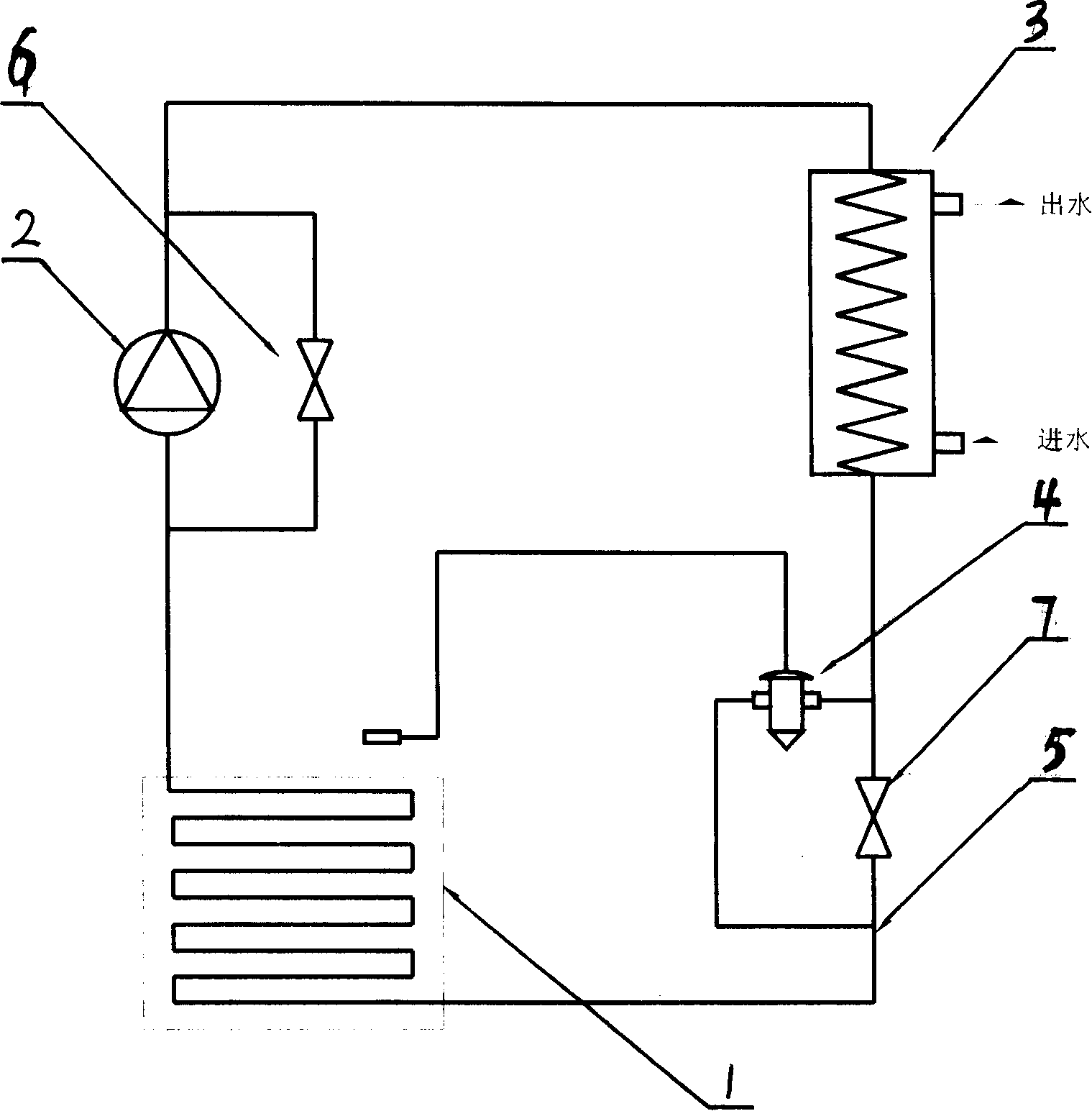
[0013] The device can work in two modes according to different external conditions, that is, a heat pipe mode and a heat pump mode.

[0014] Heat pipe working condition: the compressor is stopped, the vapor phase bypass valve (6) and the liquid phase bypass valve (7) are opened, the working medium absorbs heat and vaporizes in the evaporative heat collector under the heating of external energy, and passes through the vapor phase bypass valve. The through valve (6) enters the condenser (3), condenses into a liquid state after discharging heat to the condenser, and then flows into the evaporative heat collector (1) through the liquid phase bypass valve (7) to absorb heat and vaporize, reciprocating, heating and condensing The heated medium with a lower temperature in the device;

[0015] Heat pump working condition: When hot water is needed but the external energy is insufficient, the device works in heat pump mode. At this time, the compressor (2) is turned on, the vapor phase ...


PUM


Abstract

The invention relates to a solar energy heat tube heat pump unit and a method for accomplishing the same. The pump unit comprises an evaporation heat collecting device which can absorb the radiant heat of solar energy or the quantity of heat of other heat sources such as the waste heat and is a system evaporator and is a compressor, a throttling gear, a condenser, a system connecting pipe, a vapor phase bypass valve and a liquid phase bypass valve as well. The invention is characterized in that when the device works in a mode of heat tube, the liquid working substance inside a pipe of the heat collecting device is evaporated into steam by the radiate heat of the sun or the quantity of heat of other mediums, the steam working substance enters into the water inside a heating water tank of the condenser and condenses to liquid which returns to the evaporation heat collecting device again by the push of gravity. Therefore, the water is heated circularly. The invention works in a mode of heat pump when the heat collecting device as the evaporator is at low temperature and pressure. Therefore, the solar energy or the heat energy in other mediums can be absorbed and the medium to be heated inside the condenser is heated. The energy consumption of the heating device is 25 percent of that of the electric water heater.

Description

[0001] Field of the Invention The present invention relates to a commercial or domestic solar hot water production device. It contains an evaporative heat collector that can absorb solar heat energy and is also an evaporator, a compressor, a throttling device, a condenser, a system connecting pipe, a vapor phase bypass valve, a liquid phase bypass valve, etc. Its characteristics are: when the solar energy is abundant and the temperature of the solar collector plate is higher than the temperature of the heated water to a certain set level, the device can work in the heat pipe mode: the liquid working medium in the evaporation collector absorbs solar radiation The heat evaporates into a vapor state, and the higher-temperature vapor-state working medium enters the condenser through the vapor-phase bypass valve connected in parallel with the compressor to heat the water in the condenser. After releasing heat, it recondenses into a liquid state. Next, through the liquid-phase bypass ...

Claims


Application Information

Patent Timeline
Patent Type & Authority Applications(China)
IPC IPC(8): F25B29/00F25B27/00F28D15/02F24H4/02
Inventor 胡龙李凡
Owner 胡龙
Why Eureka
Try Eureka