
Method and system for delayed processing active electric power filter

A power filter and delay processing technology, which is applied in active power filter, harmonic reduction device, AC network to reduce harmonic/ripple, etc., can solve the problem of affecting the compensation accuracy and delay effect of active power filter Problems such as loss of compensation effect are not considered, and it is easy to realize full digitalization, ensure stability and dynamic response speed, and eliminate sampling delay

Inactive Publication Date: 2008-06-18
耿华 +2
View PDF1 Cites 31 Cited by
  • Summary
  • Abstract
  • Description
  • Claims
  • Application Information

AI Technical Summary

Problems solved by technology

However, this method compensates the harmonic current of the current cycle according to the harmonic current value of the previous cycle. When the load current changes suddenly or the time changes in the power frequency cycle, the compensation effect will be lost or even cause system instability.
At the same time, the digital active power filter needs to sample the harmonic current value output by the filter in real time to form a closed loop. The current value contains the high-order harmonics brought in by the PWM switching action of the filter. Due to the influence of high-order harmonics, the above-mentioned sampled values ​​are often digitally filtered in the DSP chip, and then the filtered value is used to form a closed loop; however, the delay effect caused by the feedback signal filtering is not considered in the system implementation. Considering that it affects the compensation accuracy of the active power filter

Method used


Image

  • Method and system for delayed processing active electric power filter
  • Method and system for delayed processing active electric power filter
  • Method and system for delayed processing active electric power filter

Examples


Embodiment Construction

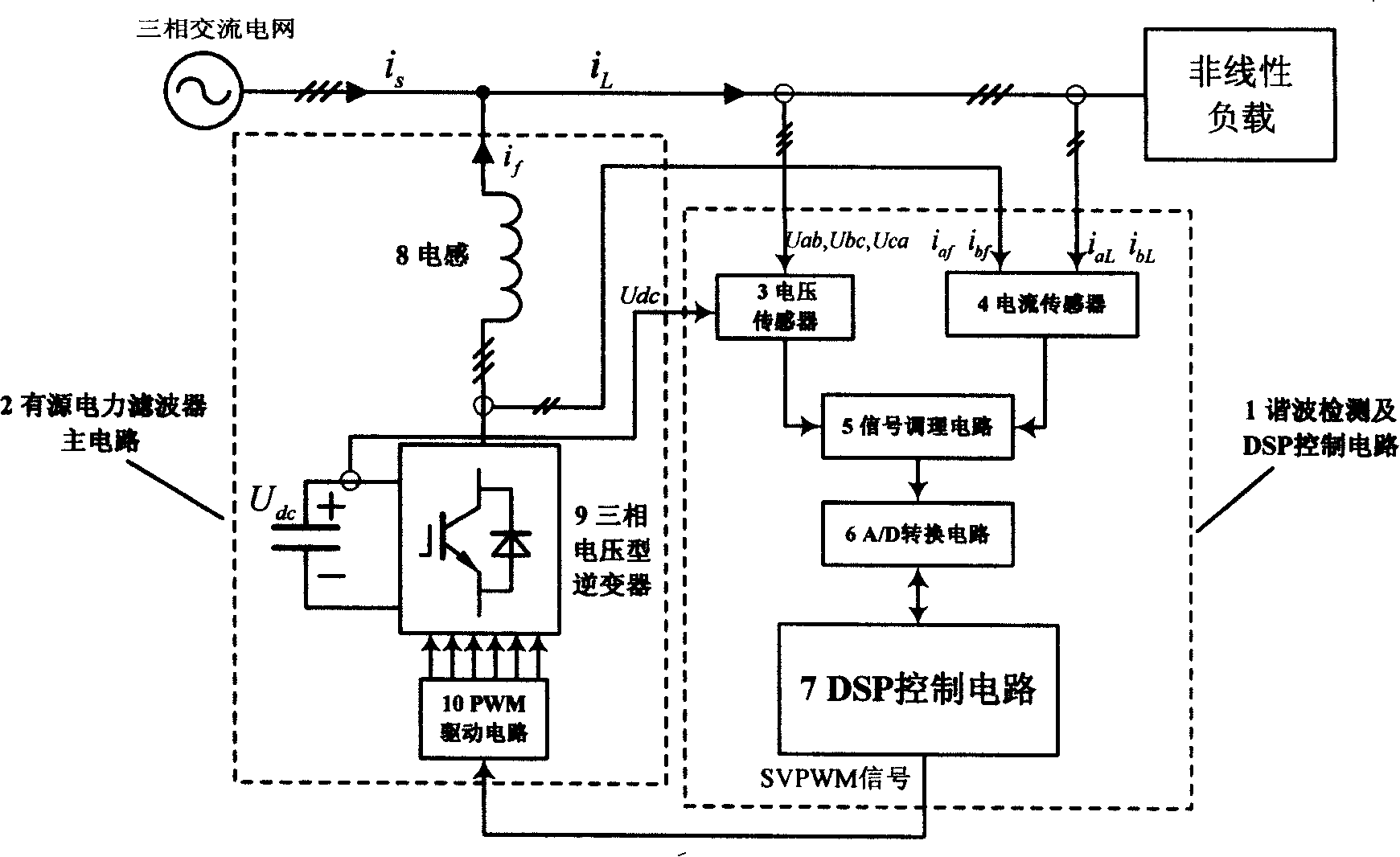
[0026] figure 1 It is the active power filter of the present invention. It is composed of a harmonic detection and DSP control circuit 1 and an active power filter main circuit 2. Harmonic detection and DSP control circuit 1 includes voltage sensor 3, current sensor 4, signal conditioning circuit 5, A / D conversion circuit 6 and DSP control circuit 7; active power filter main circuit 2 includes inductor 8, three-phase voltage type Inverter 9 and PWM drive circuit 10.

[0027] The voltage sensor 3 detects the grid voltage signal u in real time ab , u bc , u ca and the DC voltage u across the DC bus capacitor of the three-phase voltage inverter 9 dc , sent to the signal conditioning circuit 5; the current sensor 4 detects the nonlinear load current i in real time aL , i bL and active power filter output current i af , i bf , is also sent to the signal conditioning circuit 5; the signal conditioning circuit 5 is used to filter out the output signal u of the voltage sensor...


PUM


Abstract

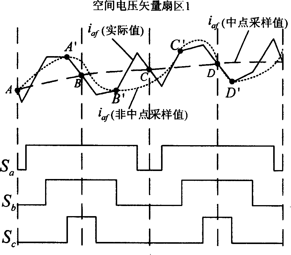
The invention discloses a disposal method used for the digital delay of an active power filter and the corresponding devices. The invention comprises the following steps that a load current is sampled by selecting a time point which is prior to the time Vt when duty cycle loading is implemented, and the current value of the load at current time is detected; the harmonic component in the load current is calculated based on a change detection algorithm; the output current of active power filter is sampled by selecting the middle-point times of all switch periods of PWM signals; close ring control is carried out for the harmonic component of the load current and the output current of the active power filter, the PWM signal is modulated and a power device is driven. By adopting the method, the effect of digital delay to the compensation precision of the active power filter is reduced; the sampling delay of the load current with periodic harmonic is eliminated; the operation time is little, and full digitization is easy to be implemented. The invention is more applicable to the microprocessor chips with medium prices and processing speed, and reduces the cost of active power filter.

Description

Technical field: [0001] The invention relates to a delay processing method and system of an active power filter, belonging to the technical field of power electronics. Background technique: [0002] The wide application of power electronic devices has brought a large number of harmonics to the power grid, and the problem of harmonic pollution has attracted people's attention. As early as 1993, my country passed the harmonic pollution standard for limiting power supply systems and electrical equipment - "Power Quality Harmonics in Public Power Grids" (GB / T-14594-93). For a long time, traditional passive filters have played a great role in power grid harmonic control. However, with the development of modern industry, power loads are becoming more and more complex, and power system harmonics are more time-varying. Passive power filters Due to the poor dynamic performance and the risk of resonance, the application is limited to a certain extent. Active power filter, as a devic...

Claims


Application Information

Patent Timeline
IPC IPC(8): H02J3/01
CPCY02E40/40Y02E40/22Y02E40/20
Inventor 耿华郭希铮王飞
Owner 耿华
Learn More