Apparatus for and method of deep groove welding for increasing welding speed

A welding equipment and equipment technology, applied in welding equipment, arc welding equipment, welding accessories, etc., can solve problems such as unsuitable deep and narrow groove welding, unstable metal transmission, etc.

Inactive Publication Date: 2008-07-16
GENERAL ELECTRIC CO
View PDF0 Cites 4 Cited by
  • Summary
  • Abstract
  • Description
  • Claims
  • Application Information

AI Technical Summary

Problems solved by technology

However, due to the arc associated with the interaction of adjacent magnetic fields, the instability of metal transport, and the variation in the energy of the arc corresponding to each filament, closely adjacent twin-wire welding is not suitable for applications such as deep narrow grooves using a single conventional power source. Welding Applications

Method used


Image

  • Apparatus for and method of deep groove welding for increasing welding speed
  • Apparatus for and method of deep groove welding for increasing welding speed

Examples


Embodiment Construction

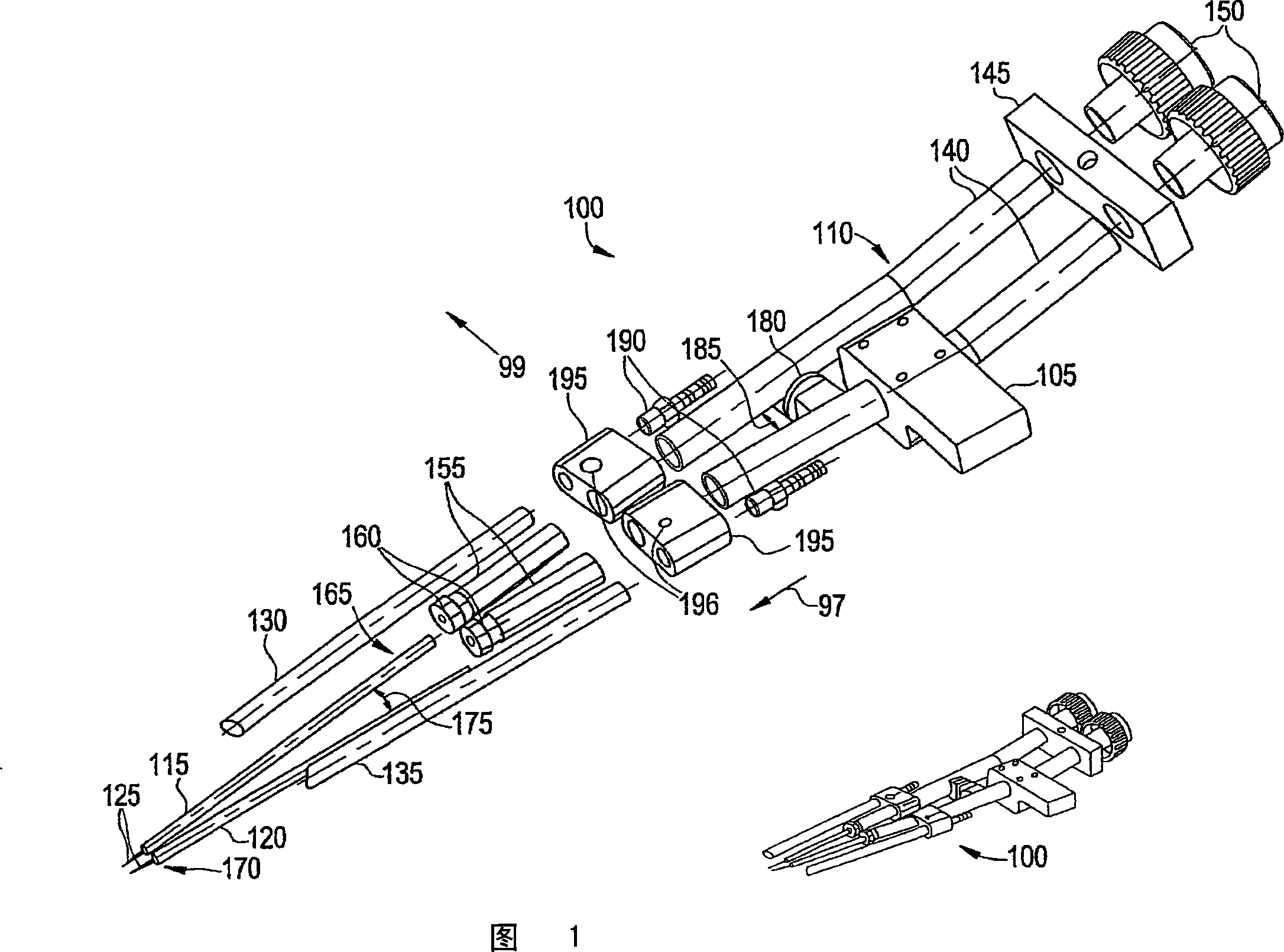
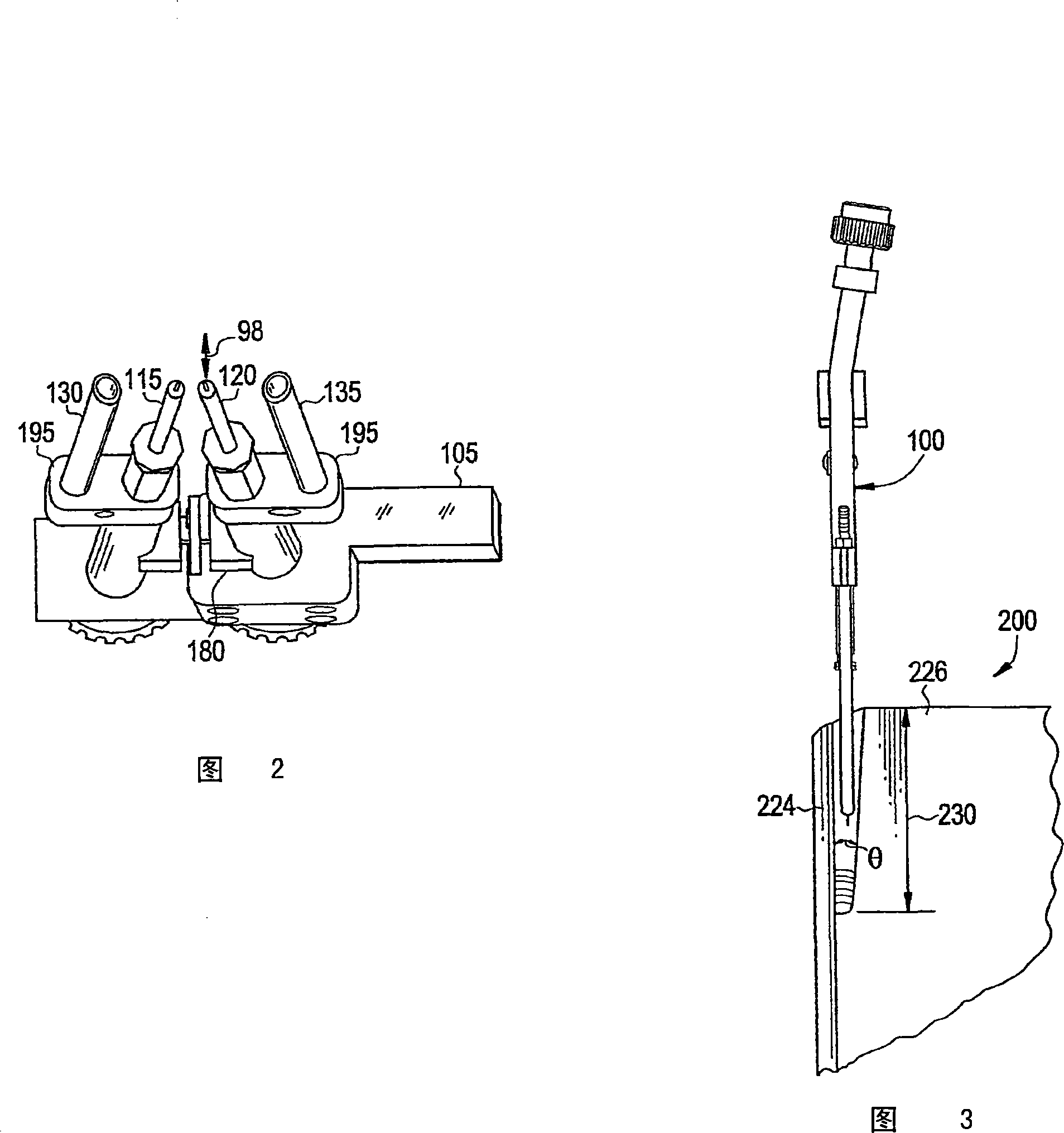
[0012] One embodiment of the present invention will provide a welding torch and process for narrow slot MIG welding using two filaments fed into a common molten pool of welding material. The welding torch is able to operate in a narrow slot to reduce the required welding time compared to currently used single filament MIG welding systems. In an embodiment, the process facilitates improved welding productivity due to higher welding speed and higher deposition rate of the filament. In one embodiment, each filament is connected to its own power supply to enable independent adjustment of welding voltage, current level and welding power delivery waveform, such as a continuous or pulse modulated power delivery waveform.

[0013] In one embodiment, the composition of the deposited metal can be tailored by independently varying at least one of filament diameter, alloy content, and feed rate for each of the two separate contact tips for improved metallurgy and mechanical properties. ...


PUM


Abstract

The present invention relates to equipment and methods for deep groove welding. Disclosed is a welding device. The welding device includes a welding torch body (110) having at least one core (140), a plurality of contact tips (115) (120) extending in a direction from the at least one core (140), and (115)(120) a plurality of gas supply tubes (130)(135) arranged, the plurality of gas supply tubes (130)(135) extending in a direction substantially similar to the plurality of contact tips (115)(120).

Description

technical field [0001] The present disclosure relates generally to welding, and in particular to deep groove welding. Background technique [0002] Gas metal arc welding, including metal inert gas (MIG) welding, employs a consumable filament, also referred to herein as a filament, a power source, and a system for directing shielding gas to the weld zone. Filament and shielding gas are continuously fed into the weld zone through a "torch" electrically connected to a power source. The workpiece is connected by a ground wire, which completes a circuit with the power supply. The filament is held at a potential above ground using a power source capable of supplying the appropriate amount of current to create the arc. When the filament touches the workpiece, an arc is formed which melts the localized metal of the workpiece and the filament, forming a molten pool which then cools to form the weld. The shielding gas protects the molten pool from oxidation and provides at least on...

Claims


Application Information

Patent Timeline
Patent Type & Authority Applications(China)
IPC IPC(8): B23K9/173
CPCB23K9/0213B23K9/124B23K9/1735B23K9/16B23K9/173B23K9/26B23K9/32
Inventor L·B·斯皮格尔E·K·艾利斯W·H·蔡尔兹P·R·伯克
Owner GENERAL ELECTRIC CO
Why Eureka
Try Eureka