Spring lamination pair for microminiaturization voice coil motor

A technology of spring leaf and voice coil, applied in the field of spring leaf, can solve the problems of difficulty in ensuring the actual production quality, low assembly process cost, and large number of parts, so as to improve the displacement distance and response speed, reduce the number and The effect of processing technology and saving processing materials

Inactive Publication Date: 2008-07-23
惠州龙德科技股份有限公司
View PDF0 Cites 17 Cited by
  • Summary
  • Abstract
  • Description
  • Claims
  • Application Information

AI Technical Summary

Problems solved by technology

[0006] It is not difficult to see from the above prior art that although the existing voice coil motor can provide the required linear displacement, it still has the following main defects: a) the number of parts required is large, it is difficult to further reduce the space in the structure, and the process implementation The performance is poor, and the actual production quality is difficult to guarantee; b) Since the front and rear springs that make up the spring pair are flat-shaped structures, separate positive and negative input terminals are required to complete the current introduction function, which undoubtedly increases the number of parts ; c) Both the front and rear spring pieces participate in the current circuit, so a separate insulating piece is required to insulate them from the metal shell; d) The positive terminal and the negative terminal are respectively connected to the front spring piece and the rear spring piece by

Method used


Image

  • Spring lamination pair for microminiaturization voice coil motor
  • Spring lamination pair for microminiaturization voice coil motor
  • Spring lamination pair for microminiaturization voice coil motor

Examples


Embodiment Construction

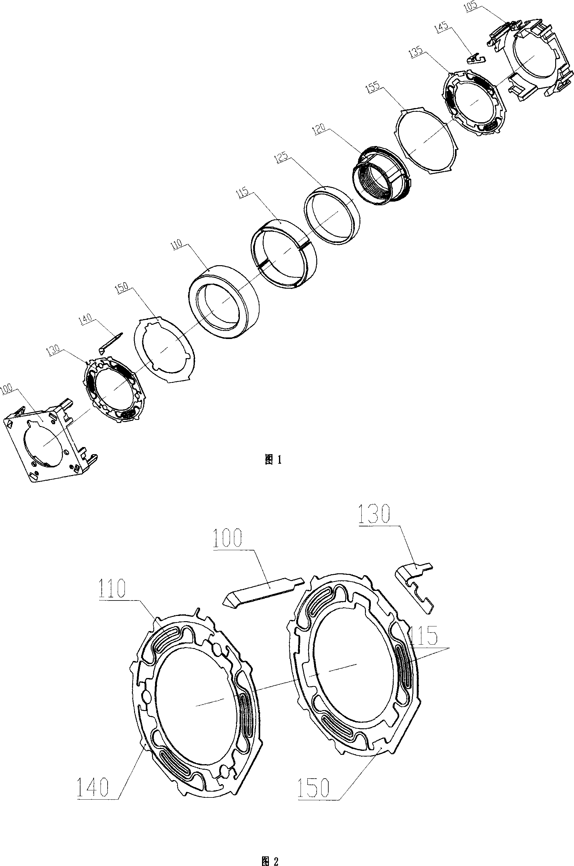
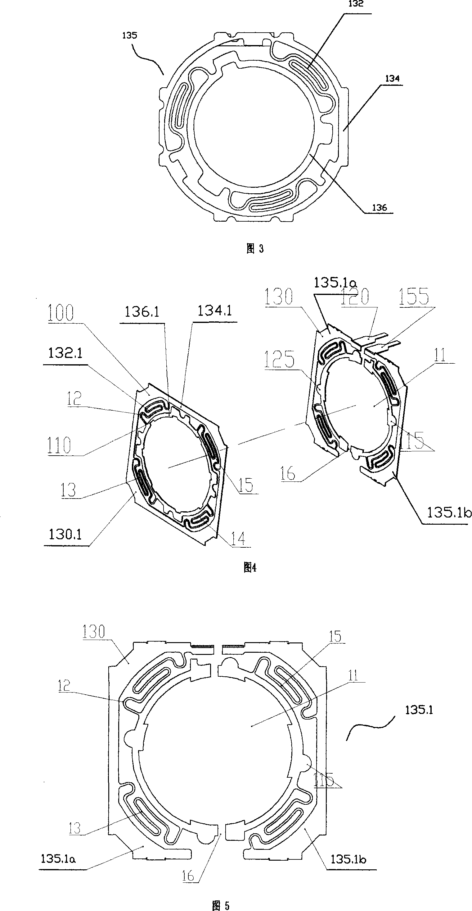
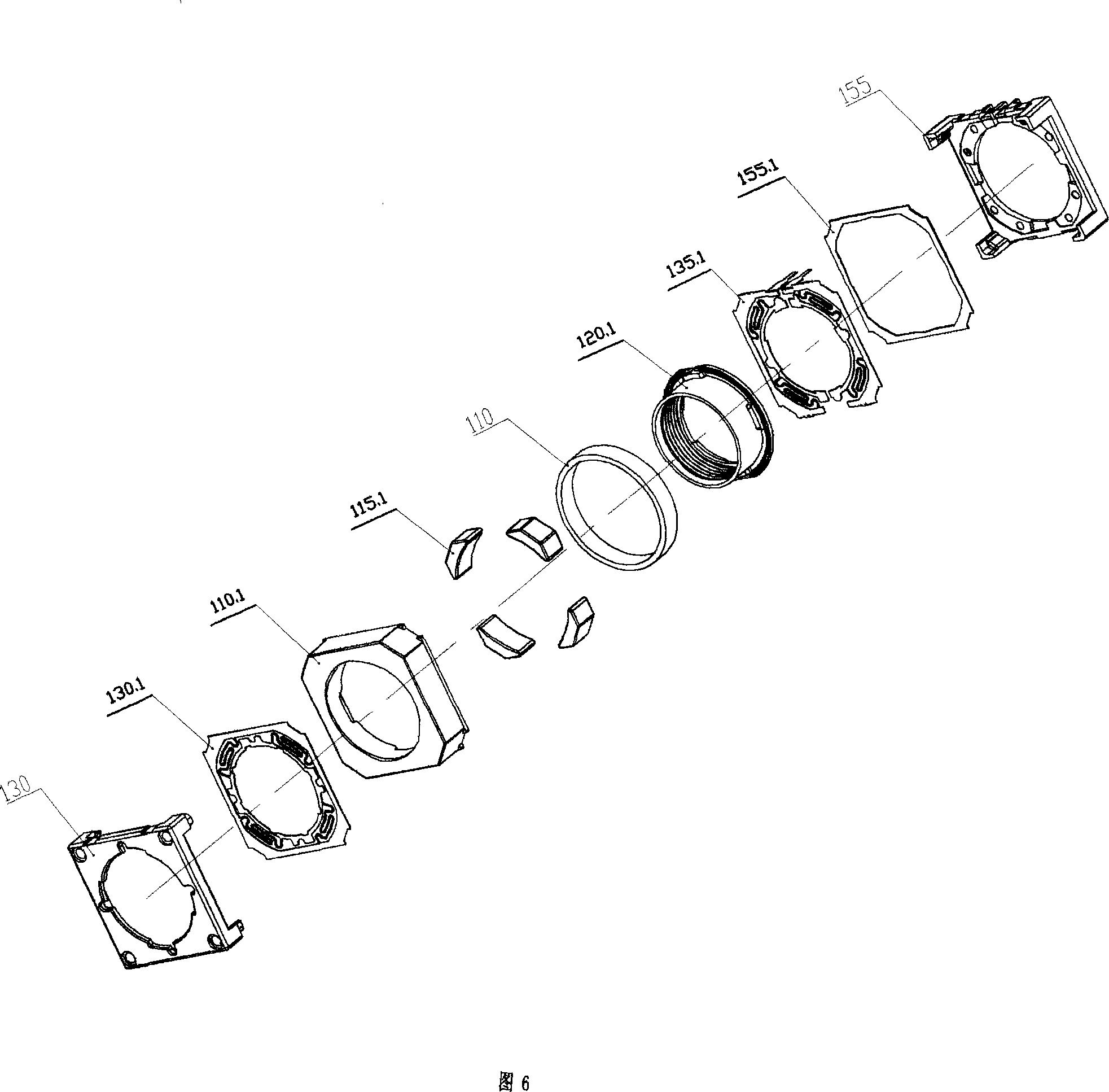
[0039]As shown in Fig. 4 and Fig. 5, the utility model includes: a front spring sheet 130.1 and a rear spring sheet 135.1, and the front spring sheet 130.1 and the rear spring sheet 135.1 all include a flat substrate 10, and the substrate can be a copper-tin-nickel alloy It is made of sheet, which has excellent elasticity, fatigue resistance, electrical conductivity, easy welding, and oxidation resistance. There is a center hole 11 in the center of the base body, and the outer periphery of the center hole 11 is coaxially distributed with an inner ring moving ring 136.1 and an outer ring fixing ring 134.1 radially from the inside to the outside. The inner ring moving ring 134.1 is provided with at least one clip position structure 20, the inner ring moving ring 136.1 can rely on the concave-convex locking structure 20 and the moving seat 120 to achieve radial positioning, and rely on the pressing of the front and rear brackets 100, 105 to achieve axial positioning; the outer rin...


PUM


Abstract

A spring lamination pair for a microminiature voice coil motor comprises a front and a rear spring laminations, wherein the front and rear spring laminations both comprise a base body which is opened with a central hole on the center, an inner circle moving ring and an outer circle fixing ring are distributed on the same axis from inner to outer along the peripheral radial direction of the central hole, the inner circle moving ring is provided with a clipping position structure, and the outer circle fixing ring is provided with a tortuous spring wire. The invention is characterized in that the rear spring lamination is formed by combining two half of spring laminations whose left and right are separated through a sheet separating insulating groove, and each half spring lamination is respectively connected with positive and negative input ends. The front and rear spring lamination base bodies are all rectangle plane structure, the outer circle fixing ring is provided with at least four interlaced and tortuous spring wires, each tortuous spring wire has same shape, which is evenly and symmetrically distributed between the inner circle moving ring and outer circle fixing ring. The invention is adopted to increase response speed of a moving carrier base, reduce component number and processing procedure of a voice coil motor, save processing material, reduce manufacturing cost and also reduce external dimension of the voice coil motor.

Description

【Technical field】 [0001] The invention relates to the field of voice coil motors, in particular to an ultra-miniature spring leaf pair of voice coil motors that undertakes the auto-focus function in auto-focus camera modules of portable electronic devices such as mobile phones and notebooks. 【Background technique】 [0002] Voice Coil Motor (VCM) is a special linear displacement drive motor, which has the advantages of simple structure, small size, low energy consumption, no noise, high acceleration and fast response, accurate displacement and low price. Voice coil motors are ideal as short-distance linear displacement power units in portable electronics. Currently, autofocus camera modules for mobile phones and notebook computers generally use voice coil motors as the power unit for the displacement of their optical devices. However, the driving / restoring change speed of the voice coil motor is relatively slow compared with the change speed of several milliseconds in portab...

Claims


Application Information

Patent Timeline
IPC IPC(8): H02K33/00H02K33/18F16F1/02
Inventor 刘宏伟卢致辉
Owner 惠州龙德科技股份有限公司
Why Eureka
Try Eureka