Low consumption permanent magnetism biased axial radial magnetic bearing

A permanent magnet offset, axial-radial technology, applied in the direction of shaft and bearing, bearing, shaft, etc., can solve the problems of long axial length of rotor, large eddy current loss, increased magnetic bearing loss, etc., and achieve high critical speed. , The effect of low bearing loss and simple structure

Inactive Publication Date: 2008-08-06
NANJING COLLEGE OF CHEM TECH
View PDF0 Cites 26 Cited by
  • Summary
  • Abstract
  • Description
  • Claims
  • Application Information

AI Technical Summary

Problems solved by technology

[0004] At present, there are two structural forms of permanent magnet bias axial radial magnetic bearings studied internationally. One is to separate the radial magnetic bearing from the axial magnetic bearing, and use the same permanent magnet to provide radial and axial bias. The magnetic flux is set. This structure has a long axial length of the rotor and a low critical speed of the rotor; the other is to integrate the axial and radial directions together, which has a compact structure and a small volume, greatly improves the dynamic performance of the rotor, and reduces the cost of the bearing. In order to facilitate the radial control winding of this kind of magnetic bearing, there is a gap between the radial stator poles, resulting in the tooth harmonic component in the air gap magnetic density. When the rotor rotates, it is alternately under the stator teeth or the gap, and its The magnetic density on the rotor alternates at a high frequency, and the alternating magnetic density will generate a large eddy current loss on the rotor core, resulting in an increase in the loss of the magnetic bearing

Method used


Image

  • Low consumption permanent magnetism biased axial radial magnetic bearing

Examples


Embodiment Construction

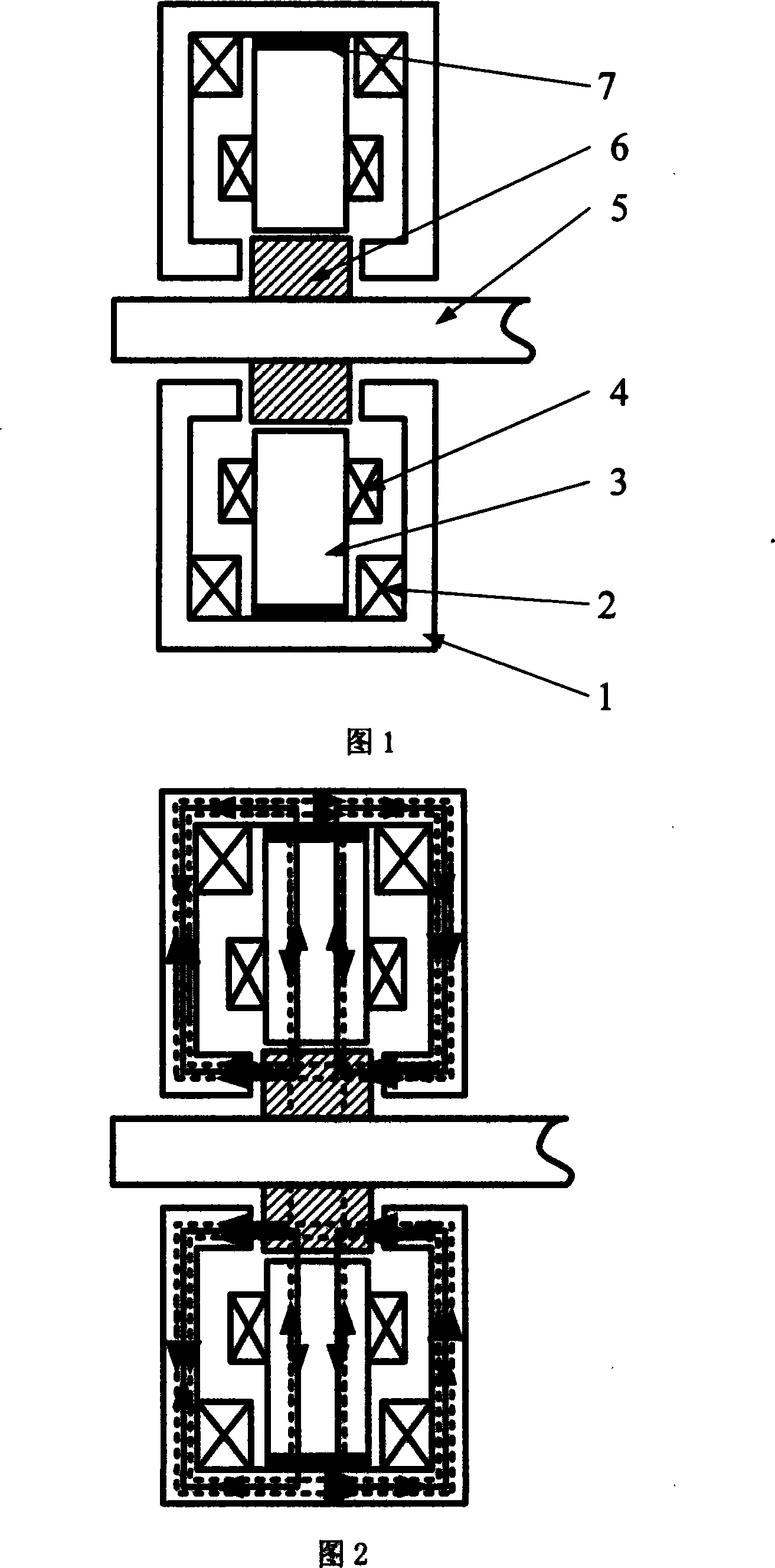
[0012] Fig. 1 is a schematic structural view of the low-loss permanent magnet bias axial radial magnetic bearing of the present invention, the axial stator pole 1 in the figure is made of electric iron, and two axial control windings 2 are sheathed on the axial stator pole. The control windings 2 are connected in series, the inner end surface of the axial stator is in contact with the annular permanent magnet 7, and the annular permanent magnet is mounted on the outer end of the radial stator 3, and the radial stator is a four-pole structure with no gaps between the magnetic poles. Silicon steel sheets are stacked, and each pole is wound with a control winding 4 respectively. The rotor core 6 is stacked by silicon steel sheets and is set on the rotor 5 and placed in the stator 1 and the stator 3 . The bias flux generated by the annular permanent magnet passes through the axial pole core, the rotor core, the radial air gap and the radial stator in turn to form a circuit, as show...


PUM


Abstract

The invention relates to a low loss permanent magnet biased axial radial magnetic bearing, which belongs to a mixed magnetic bearing, which comprises an axial stator (1), an axial control winding (2), a radial magnetizing ring permanent magnet (7), a radial stator (3), a radial control winding (4) and a rotor (5) which is sleeved with an iron core (6). The low loss permanent magnet biased axial radial magnetic bearing uses the radial magnetizing ring permanent magnet to build a static bias magnetic field, a closed magnetic circuit is formed through an external axial pole core, a rotor iron core and a radial stator, and the axial control winding produces a controlling flux and a bias flux which are stacked to control axial suspension. A control winding is surrounded on a radial stator of a four-tooth two-antipode structure which is not retained gaps between magnetic poles, the windings on the two corresponding teeth are connected in series, and the superposition of the controlling flux and the bias flux are produced to achieve radial two freedom suspension. The structure is simple, the critical speed is high, the power consumption is low, and the low loss permanent magnet biased axial radial magnetic bearing has wide application prospect in high speed application fields which are flywheel energy storage, air conditioning compressors and turbomolecular pumps and the like.

Description

technical field [0001] The low-loss permanent magnet bias axial radial magnetic bearing of the invention belongs to the hybrid magnetic bearing in the magnetic bearing. 2. Background technology [0002] Magnetic suspension bearing, also referred to as magnetic bearing for short, is a new type of high-performance bearing that uses the magnetic force between the stator and the rotor to suspend the rotor in space, so that there is no mechanical contact between the stator and the rotor. Because there is no mechanical contact between the stator and the rotor, the rotor of the magnetic suspension bearing can reach a high operating speed, and has the advantages of small mechanical wear, low energy consumption, long life, no lubrication, no pollution, etc., especially suitable for high speed , vacuum and ultra-clean and other special applications. [0003] At present, magnetic bearings are divided into the following types according to the way the magnetic force is provided: The fir...

Claims


Application Information

Patent Timeline
Patent Type & Authority Applications(China)
IPC IPC(8): F16C32/04
CPCF16C32/0465F16C32/0485F16C2360/45
Inventor 赵旭升蒋汝根王永红尹俊殷杰
Owner NANJING COLLEGE OF CHEM TECH
Why Eureka
Try Eureka