Blowing out device system for air conditioner, heat removal transmission device system and air conditioning system with the same

A heat transfer and air conditioning technology, applied in air conditioning systems, space heating and ventilation control input, household heating, etc. It can solve problems such as difficult setup, increased equipment costs, and difficulty in individual control, and achieve good temperature management.

Inactive Publication Date: 2008-08-06
MITSUBISHI ELECTRIC CORP
View PDF4 Cites 19 Cited by
  • Summary
  • Abstract
  • Description
  • Claims
  • Application Information

AI Technical Summary

Problems solved by technology

[0013] However, in the air conditioning system proposed in Patent Document 1, since the hot air is induced by the guider that completely covers the server group, it is necessary to make the surfaces forming the exhaust ports on the server side uniform (height). , Inhale the hot air discharged from each server, and guide it to the suction port of the air conditioner. In the server room where servers of various specifications are mixed, it is difficult to install, or it is necessary to install a large-scale guide, so , there is a problem of increased equipment cost
[0014] In addition, in the conventional air conditioning system proposed in Patent Document 2, when the exhaust heat from the server staying near the roof of the server room is induced to the suction port of the air conditioner, it is induced only by the suction force of the air conditioner. , there is a problem that the indoor temperature rises around the roof
[0015] In addition, in the method of using ducts in Patent Document 3 to directly send the cold air in the air supply chamber to the high-temperature part of the room, the cold air can be reliably sent to the heat-generating equipment, and the local concentration or heat load distribution in the server room can be reduced. Unevenness, but on the contrary, there is a problem that the cost of equipment increases because piping is required for each machine
In addition, because this device alone cannot return the hot air from the servers staying near the roof of the server room to the air conditioner suction port, there is a problem that the warm environment in the upper part of the room cannot be improved.
[0016] In addition, in the system proposed in Patent Document 4, which detects environmental information such as the temperature of the air-conditioned area, controls the amount of cold air supplied by the air-conditioning unit from a plurality of air outlets that can control the air volume, and performs air conditioning. It is possible to control each area individually, but there is a problem that the cost of equipment increases because piping is required for each machine
In addition, since the air-conditioning control from the under-floor air supply chamber of the under-floor air-conditioning system is performed, there is a problem that it is difficult to perform a separate damper because there are blow-out openings in the entire floor area in order to use this system. For regulation control, when the air blower that detects the static pressure signal on the outlet side or the passing wind speed, controls the rotation speed, and performs static pressure control is installed on the air conditioning unit side, the static pressure to the entire outlet increases, so it is difficult to perform each area. separate control
[0017] Furthermore, in the last-mentioned method in which each blowing device detects the temperature and operates, there is a problem that the air-conditioning balance of the entire room is disrupted, and the temperature rises in the area where the blowing device is not installed. In some cases, or because the hot air stagnant near the roof of the server room is not enough to return to the suction port of the air conditioner only by the blowing device, the warm environment in the upper part of the room cannot be improved.

Method used


Image

  • Blowing out device system for air conditioner, heat removal transmission device system and air conditioning system with the same
  • Blowing out device system for air conditioner, heat removal transmission device system and air conditioning system with the same
  • Blowing out device system for air conditioner, heat removal transmission device system and air conditioning system with the same

Examples


Embodiment approach 1

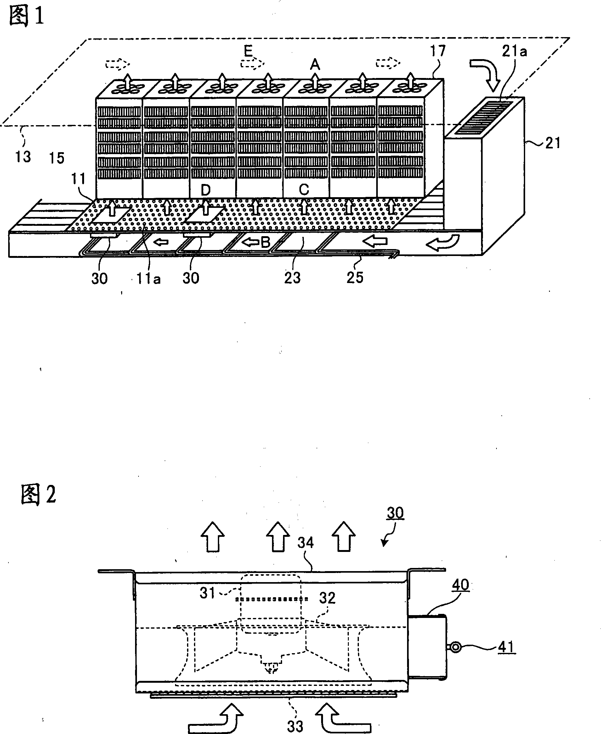
[0076] FIG. 1 is a perspective view of a server room to which the underfloor air conditioning system according to Embodiment 1 of the air-conditioning blowing device system according to the present invention is applied. The server room (electronic computer room) has an indoor space 15 formed between the floor 11 and the roof 13 . Floor 11 is a double construction floor. In the server room, a plurality of server cabinets (cabinets) 17 accommodating servers (electronic computers) therein are arranged in a row. Then, the server rack group in which the plurality of server racks 17 are arranged is provided in a plurality of rows (only one row is shown in FIG. 1 ). Each server cabinet 17 sucks in air from the suction ports formed on the bottom surface and the front surface, and releases hot air as indicated by arrow A from the air outlet formed on the upper surface.

[0077] The air conditioner 21 is installed along the side wall surface of the server room. The air conditioner 21...

Embodiment approach 2

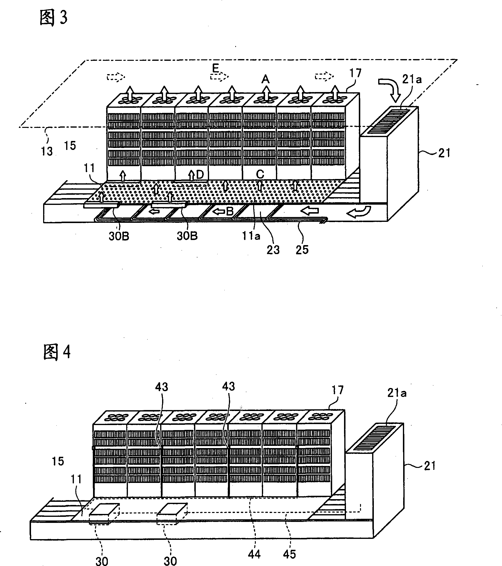
[0086] 3 is a perspective view of a server room to which the under-floor air-conditioning system according to Embodiment 2 of the air-conditioning blowing device system according to the present invention is applied. In the present embodiment, the blowing device is the blowing device 30B composed of an elongated cross-flow fan. The rest of the configuration is the same as that of the first embodiment.

[0087] According to the air-conditioning blowing device system configured in this way, substantially the same effects as those of the air-conditioning blowing device system of the first embodiment can be obtained, and since the amount of protrusion of the blowing device 30B into the air supply chamber 23 is reduced, the air supply chamber 23 The stagnation of cold air in the interior is further reduced, and by supplying less power, the amount of cold air blown out can be made the same in all places in the room.

Embodiment approach 3

[0089] 4 is a perspective view of a server room to which the under-floor air-conditioning system according to Embodiment 3 of the air-conditioning blowing device system according to the present invention is applied. In the present embodiment, as shown in FIG. 4 , temperature sensors (temperature measuring units) 43 that detect temperatures at a plurality of indoor locations are provided. Then, the temperature sensor 43 is connected to the blowing device 30 through the cable 44 . In addition, the blowing device 30 is connected to the air conditioner 21 via the cable 45 . In the blowing apparatus 30, similarly to Embodiment 1, the blowing control part (not shown) is provided. The rest of the configuration is the same as that of the first embodiment.

[0090] In this way, in the present embodiment, the amount of cold air blown out of the air conditioner 21 and the temperature information at a plurality of indoor locations are transmitted to the blowing control unit (not shown) ...


PUM


Abstract

The invention provides a blowing device system for air-conditioner, which is able to equalize the cooling air amount blown to the indoor space. In the invention, the blowing device system for air-conditioner includes an air-conditioner (21), an air-supply chamber (23), a plurality of blowing-out devices (30), an air flow measurement part and a blowing-out control part; the air-conditioner (21) inhales the air from an inhalation hole (21a) and blows out the cooling air from a blowing-out hole; the air-supply chamber (23) is formed under the ground and ventilates the air-conditioner (21), in the meantime, the cooling air is blown out to the indoor space (15) through a plurality of blowing-out holes (11a) formed on the floor; the plurality of blowing-out devices (30) inhale the cooling air in the air-supply chamber (23) and blows out to the indoor space (15); the air flow measurement part measures static pressure or wind speed of the cooling air within the air-supply chamber (23); the blowing-out control part, in accordance with the output of the air flow measurement part, enables the blowing-out devices near a stated position within the air-supply chamber to operate when the static pressure or wind speed of the cooling air at the stated position within the air-supply chamber is less than or equal to the limit value, so that the cooling air within the air-supply chamber is blown to the indoor space.

Description

technical field [0001] The present invention relates to an air-conditioning blower system for an electronic computer room in which a cabinet for accommodating an electronic computer is installed, and an under-floor air-conditioning system is adopted, and a heat exhaust conveying device that moves the hot air accumulated in the upper part of the indoor space to the suction port of the air conditioner. A system and an air-conditioning system having these air-conditioning blowing device systems and exhaust heat conveying device systems. Background technique [0002] FIG. 11 is a perspective view of a conventional server room using an under-floor air-conditioning system as an air-conditioning system. In a large-scale server room or the like in which a large number of large computers and servers are installed, the double-structure floor 11 is often used in order to perform the wiring 25 to the server equipment. In a server room having such a double-structured floor 11, a so-call...

Claims


Application Information

Patent Timeline
Patent Type & Authority Applications(China)
IPC IPC(8): F24F13/02F24F11/04F24F11/02F24F3/044F24F11/76F24F13/068
CPCF24F11/79F24F2110/10F24F11/54F24F13/068F24F3/044
Inventor 小林茂己荒木克己石川忠昭高柳良一
Owner MITSUBISHI ELECTRIC CORP
Why Eureka
Try Eureka