Photo-etching machine projection objective wave aberration on-line detection method

A projection objective lens, wave aberration technology, applied in optomechanical equipment, microlithography exposure equipment, optics, etc., can solve problems such as slow detection speed, and achieve the effect of improving measurement accuracy, measurement accuracy and repeatability

Inactive Publication Date: 2008-08-06
BEIJING INSTITUTE OF TECHNOLOGYGY
View PDF1 Cites 36 Cited by
  • Summary
  • Abstract
  • Description
  • Claims
  • Application Information

AI Technical Summary

Problems solved by technology

However, PSI needs to control the phase shifting device to collect multiple interferograms step by step, and the detection speed is relatively slow

Method used


Image

  • Photo-etching machine projection objective wave aberration on-line detection method
  • Photo-etching machine projection objective wave aberration on-line detection method
  • Photo-etching machine projection objective wave aberration on-line detection method

Examples


Embodiment 1

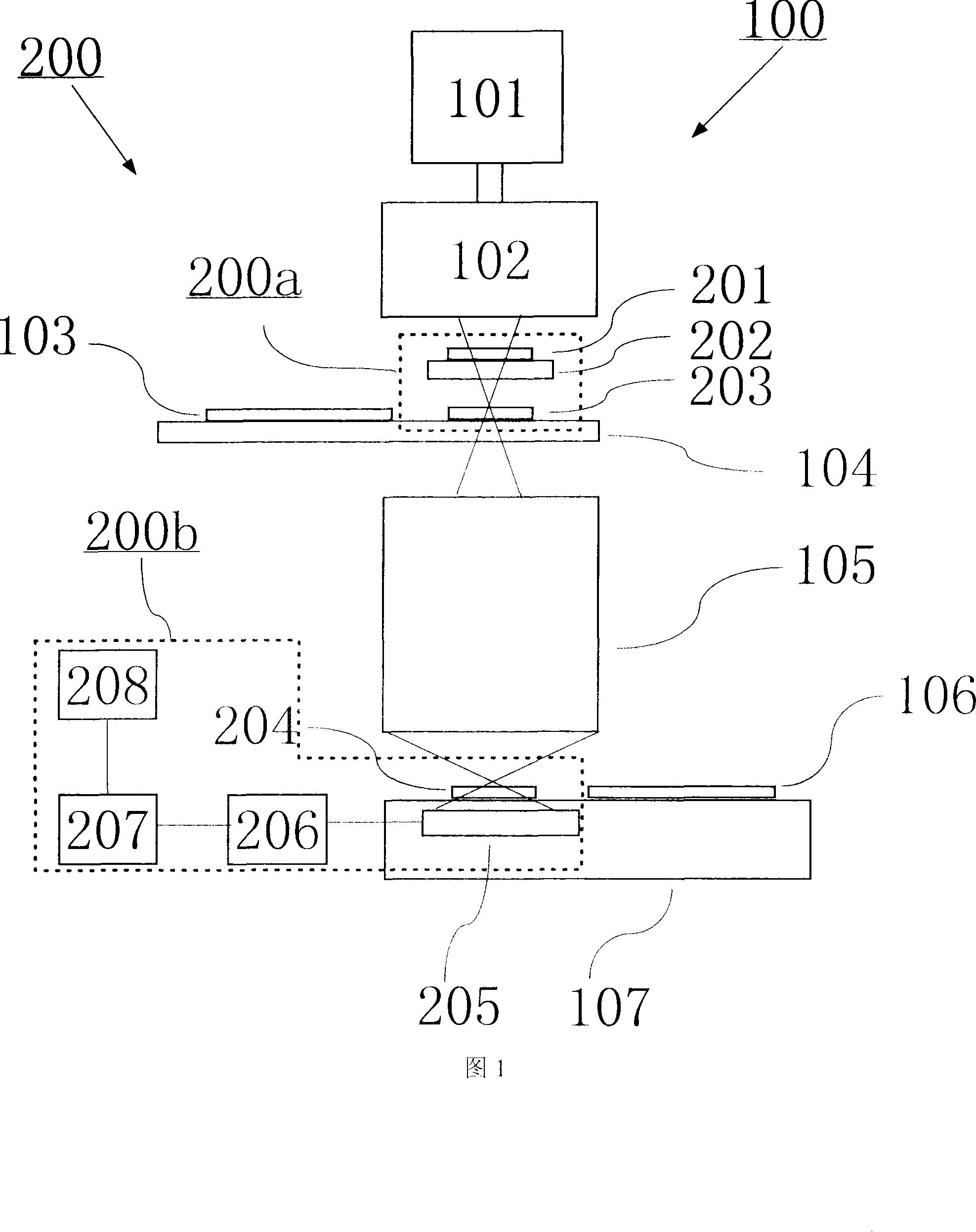
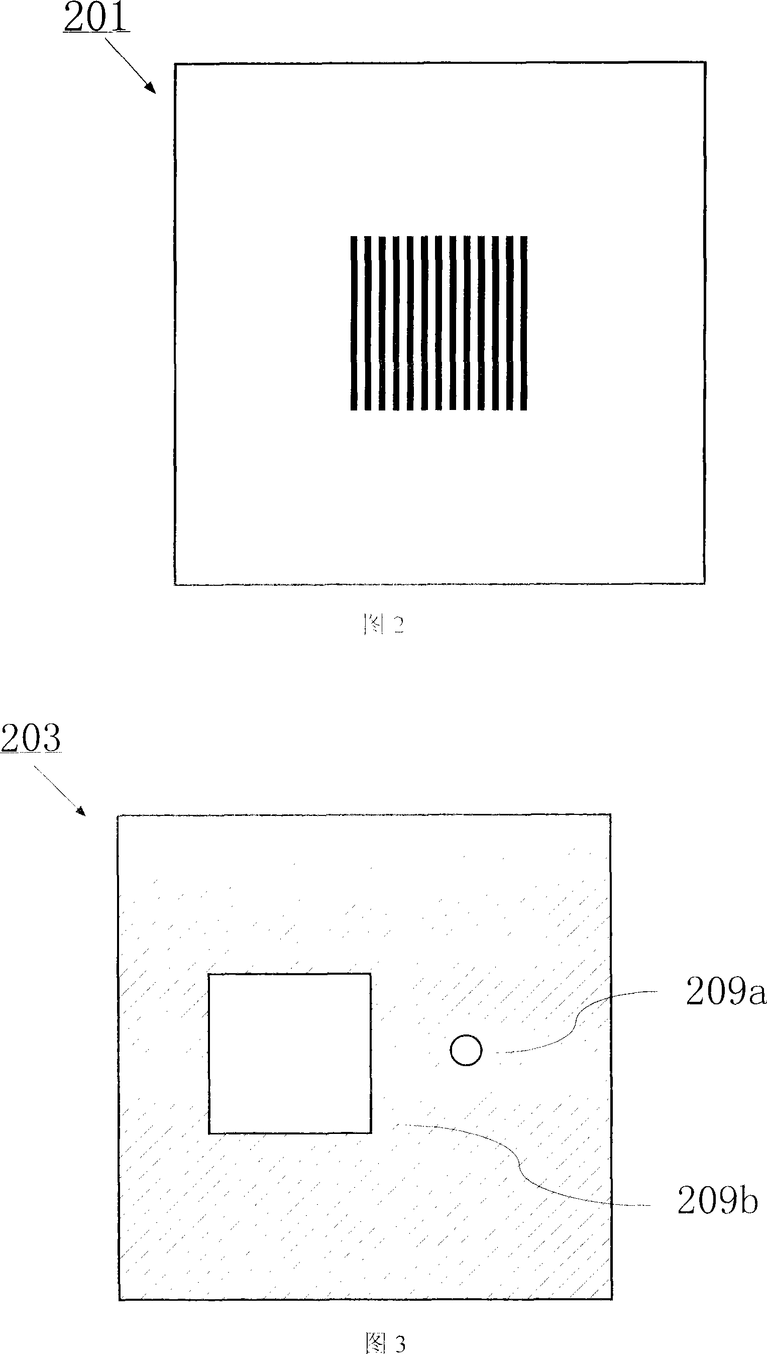
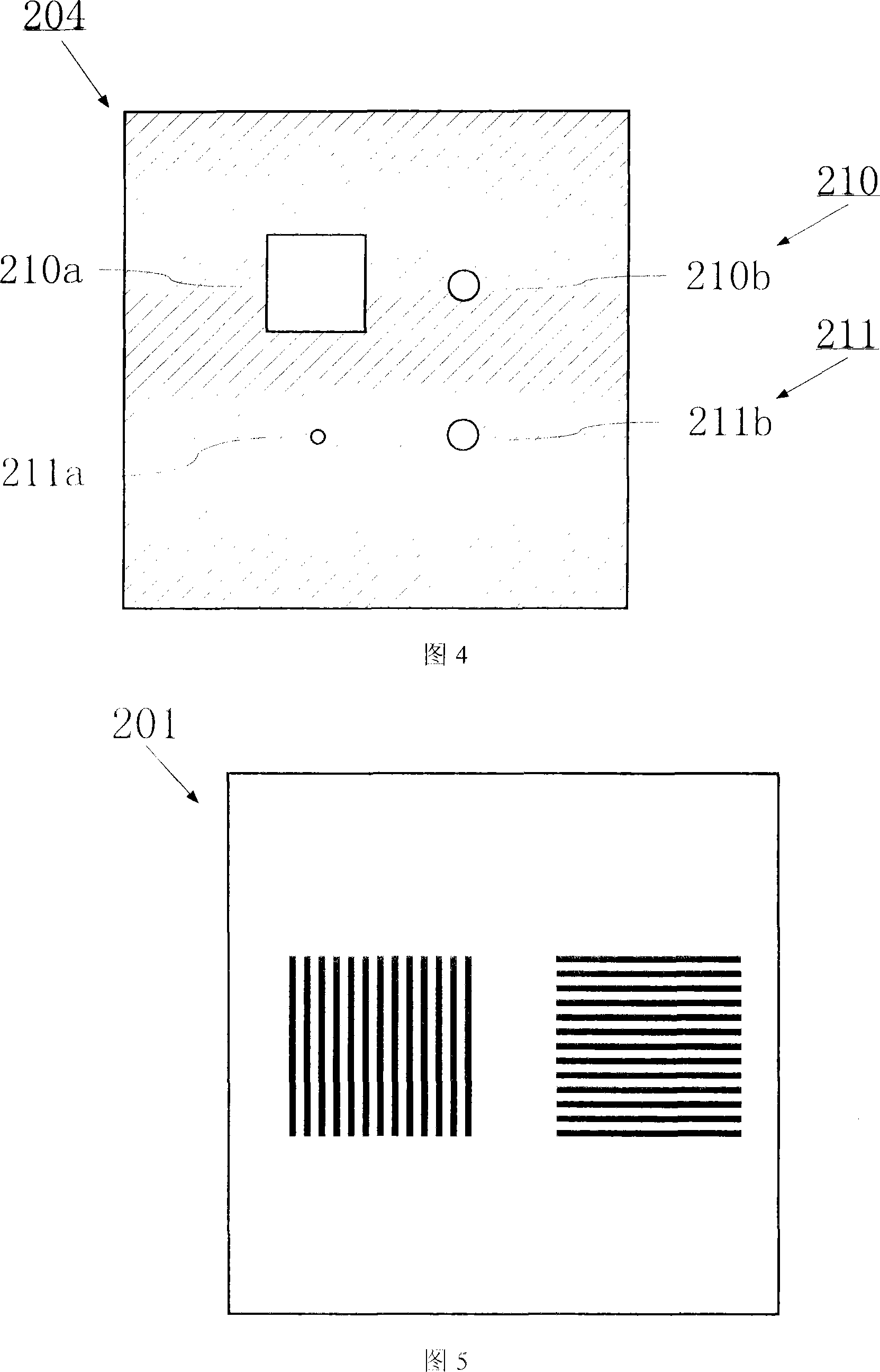
[0028] In this embodiment, an interferometer device 200 based on the principle of point diffraction interference is integrated on the lithography machine 100 to detect the wave aberration of the projection objective lens 105 online. As shown in FIG. 1 , the interferometer device 200 is structurally composed of two parts 200 a and 200 b : 200 a is integrated on the mask workpiece stage 104 , and 200 b is integrated on the silicon wafer workpiece stage 107 . The working principle of the interferometer device in this embodiment will be described below. The light beam emitted by the light source 101 is first shaped by the illumination system 102 and irradiated onto the beam splitting device 201. In this embodiment, the beam splitting device 201 is a binary grating prepared by electron beam exposure of a chromium mask, and the base material is fused silica. The light-shielding layer is metal chromium, and the chromium layer is engraved with a periodic structure with a duty ratio of...

Embodiment 2

[0059] In this embodiment, an interferometer device 200 based on the principle of slit diffraction interference is integrated on the lithography machine 100 to detect the wave aberration of the projection objective lens 105 online. The slit diffraction interferometer in this embodiment is similar in principle and structure to the point diffraction interferometer in Embodiment 1. The system error calibration method is similar to the wave aberration detection method. The differences are as follows.

[0060] In the principle of interferometer measurement, this embodiment uses a slit instead of the round hole in Embodiment 1, and uses the slit to diffract the output beam of the projection objective lens, and an ideal spherical wave is generated in the one-dimensional direction of space as a reference wave. The wave aberration of the projection objective lens is obtained by two measurements in the space orthogonal direction;

[0061] In terms of the structure of the interferometer ...


PUM


Abstract

The invention relates to an on-line detection method for detecting the wave aberration of a projection objective of a photoetching machine. The on-line detection, revising, and controlling are done to the wave aberration of the projection objective by integrating an interferometer device on the photoetching machine. The interferometer device is a point-diffraction interferometer or a slit-diffraction interferometer and is provided with two measuring modules: a PSI measuring module and an FTM measuring module. The PSI measuring module adopts phase shifting interferometry with high measuring precision and is mainly used to detect the error calibration in an interferometer device system; the FIM measuring module adopts fourier transform method to treat with interference fringes with high measuring speed, and is mainly used to on-line detect and control the wave aberration of the projection objective. The method improves the measuring precision without reducing the measuring speed, and improves the measuring precision and reproducibility of the interferometer device by adopting a higher quality spherical reference wave to calibrate the systematic error caused by each component of the interferometer device without reducing the contrast ratio of the interference fringes.

Description

technical field [0001] The invention relates to an optical performance detection method of a projection optical system, in particular to an online detection method for wave aberration of a projection objective lens of a lithography machine. Background technique [0002] The projection exposure device is used in the preparation process of large-scale integrated circuits, and the pattern on the mask is reduced and projected on the silicon wafer coated with photoresist through the projection objective lens. With the application of resolution enhancement technologies such as phase-shift masks and off-axis illumination, the process factor is gradually approaching the limit of the process, and the requirements for feature size control and overlay accuracy are getting higher and higher. The wave aberration of the projection objective lens, especially the advanced aberration, has more and more influence on the control error of the feature size. Therefore, it is necessary to develop...

Claims


Application Information

Patent Timeline
Patent Type & Authority Applications(China)
IPC IPC(8): G03F7/20G01M11/02
CPCG03F7/706
Inventor 李艳秋刘克刘丽辉
Owner BEIJING INSTITUTE OF TECHNOLOGYGY
Why Eureka
Try Eureka