Robot joint based on harmonic wave speed reducer

A technology of harmonic reducer and robot joints, which is applied in the direction of manipulators, components with teeth, manufacturing tools, etc., can solve the problems of increasing the difficulty of processing, low transmission efficiency, and difficulty in realization, and achieve motor life protection, single-stage The effect of large transmission ratio and broad application prospects

Inactive Publication Date: 2008-09-17
HARBIN ENG UNIV
View PDF0 Cites 43 Cited by
  • Summary
  • Abstract
  • Description
  • Claims
  • Application Information

AI Technical Summary

Problems solved by technology

There are also some relevant reports in the Chinese patent literature, which include the transmission of rope pulley drive, linkage mechanism transmission, belt transmission, chain transmission, etc., but no technical solution for the joint structure of the robot using harmonic reducers has been found.
[0009] Disadvantages of the rope transmission method: 1. There is tension, easy to deform, and will cause hysteresis in the transmission. Once the use time is too long, the rope will become slack, and it will bring a large motion transmission error
2. The rope can only be pulled but not compressed. Therefore, it is difficult to realize the return stroke. Once the control force is overshooted, it is difficult to eliminate it, but the overshoot phenomenon is inevitable in practice.
[0010] Disadvantages of the connecting rod transmission method: it will make the structure of the bionic robot complicated, making the design and processing of the mechanical body structure more difficult and difficult to realize
[0011] Disadvantages of belt drive transmission mode: This transmission mode has great limitations in the application of micro-robots. The specific performance is that elastic sliding is an inherent characteristic of belt drive. Belt drive cannot maintain an accurate transmission ratio, and the transmission efficiency is low; When the same large circular force is transmitted, the contour size and the pressure on the shaft are relatively large; the belt is subject to a

Method used


Image

  • Robot joint based on harmonic wave speed reducer
  • Robot joint based on harmonic wave speed reducer
  • Robot joint based on harmonic wave speed reducer

Examples


Embodiment Construction

[0028] The present invention is described in more detail below in conjunction with accompanying drawing example:

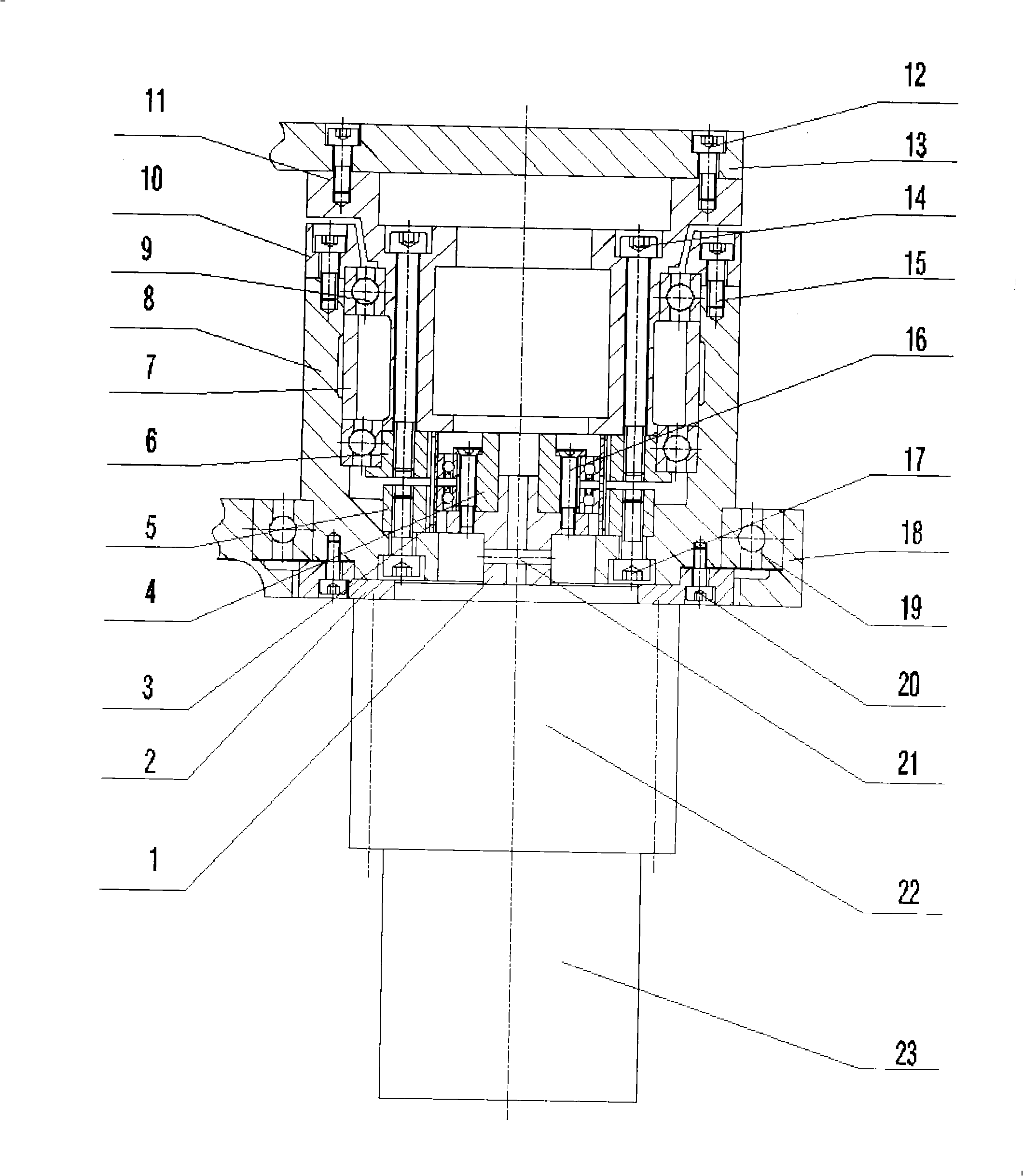
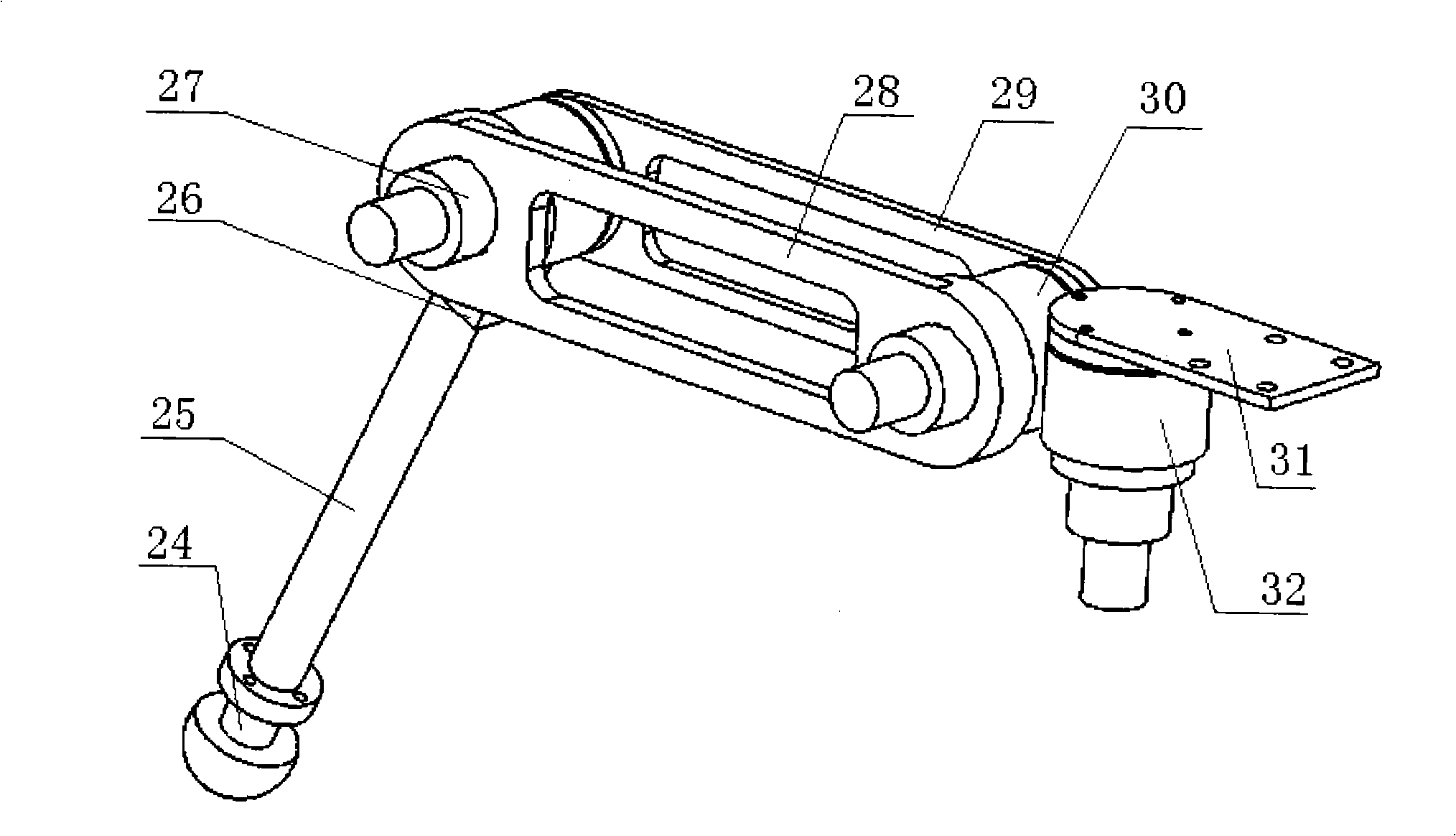
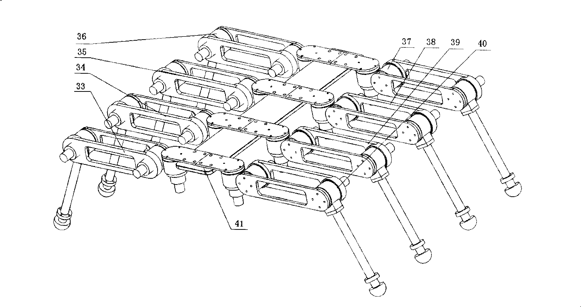
[0029] combine figure 1 , the composition of the robot joint based on the harmonic reducer mainly includes: coupling 1, motor baffle 2, flexible wheel 3, wave generator 4, fixed steel wheel 5, rotating steel wheel 6, bearing sleeve 7, shell 8 , Deep groove ball bearing 9, Bearing bracket 10, End cover 11, Hexagon socket head cylindrical screw 12, Coupling arm 13, Hexagon socket head cylindrical screw 14, Hexagon socket head cylindrical screw 15, Cross recessed countersunk head screw 16, Internal hexagon head Cylindrical screw 17, auxiliary connecting arm 18, deep groove ball bearing 19, hexagon socket head cylindrical screw 20, motor shaft connecting pin 21, motor 22 and photoelectric encoder 23.

[0030] Detailed assembly method: use a coupling 1 to connect the motor 22 through the motor shaft connection pin 21, and the other end of the coupling is connected to ...


PUM


Abstract

The invention relates to a robot joint based on harmonic reducers, which comprises a motor, an encoder connected with the motor, a harmonic reducer connected with a rotor of the motor, and a transmission mechanism connected with the harmonic reducer; wherein, the harmonic reducer comprises a wave generator, a flexible wheel outside the wave generator, a fixed steel wheel outside the flexible wheel and a rotary steel wheel; the transmission mechanism comprises a housing fixedly connected with the fixed steel wheel of the harmonic reducer and an end cover fixedly connected with the rotary steel wheel of the harmonic reducer; a bearing is arranged between the housing and the end cover. The robot joint has the advantages of high drive ratio, high reliability, compact structure, ability to substitute the robot joint in the prior art, gradual decrease with the size of the harmonic reducer, higher applicability to joint transmission of miniature robots, and wide application prospect.

Description

(1) Technical field [0001] The invention relates to a robot joint. (2) Background technology [0002] At present, the transmission modes of robot joints mainly include: rope pulley drive transmission, linkage mechanism transmission, belt transmission, chain transmission, gear transmission and so on. There are also many reports related to this aspect. There are also some relevant reports in the Chinese patent literature, which include about rope pulley drive transmission, linkage mechanism transmission, belt transmission, chain transmission transmission modes, etc., but no technical solution for the robot joint structure using a harmonic reducer has been found. [0003] The rope pulley drive transmission mode is commonly used in bionic robot joints. This transmission mode can conveniently realize the long-distance transmission of motion and power, and can better meet the structural requirements of the joints of the bionic robot. The mechanism of the rope wheel transmission...

Claims


Application Information

Patent Timeline
IPC IPC(8): B25J17/00F16H57/02
Inventor 王刚季宝锋陈东良刘德峰邓辉峰王立权陈曦
Owner HARBIN ENG UNIV
Why Eureka
Try Eureka