Electrostatic protection component, and electronic component module using the same

A technology for electronic components and resistance parts, which is applied in the direction of electrical components, electric solid state devices, circuits, etc., can solve the problems of no heat dissipation mechanism, difficult light-emitting diode heat, dissipation, etc. Excellent efficiency

Inactive Publication Date: 2008-09-17
PANASONIC CORP
View PDF1 Cites 3 Cited by
  • Summary
  • Abstract
  • Description
  • Claims
  • Application Information

AI Technical Summary

Problems solved by technology

However, chip-type components that form a relatively small package shape do not have a heat dissipation mechanism, and resin is used on the outside, so it is difficult to effectively dissipate the heat emitted by the light-emitting diodes.

Method used


Image

  • Electrostatic protection component, and electronic component module using the same
  • Electrostatic protection component, and electronic component module using the same
  • Electrostatic protection component, and electronic component module using the same

Examples


no. 1 approach

[0038] Next, the static electricity countermeasure member and light emitting diode module according to Embodiment 1 of the present invention will be described.

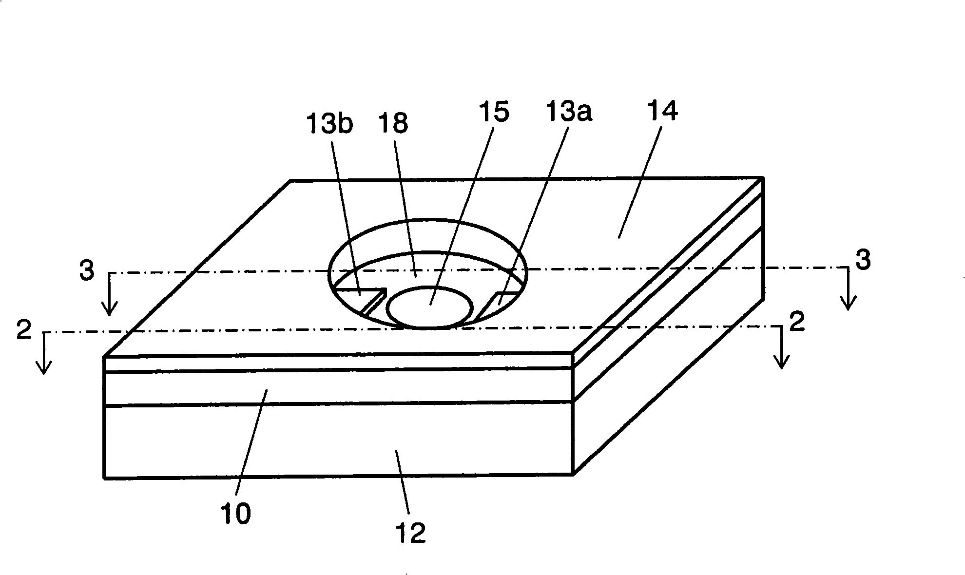
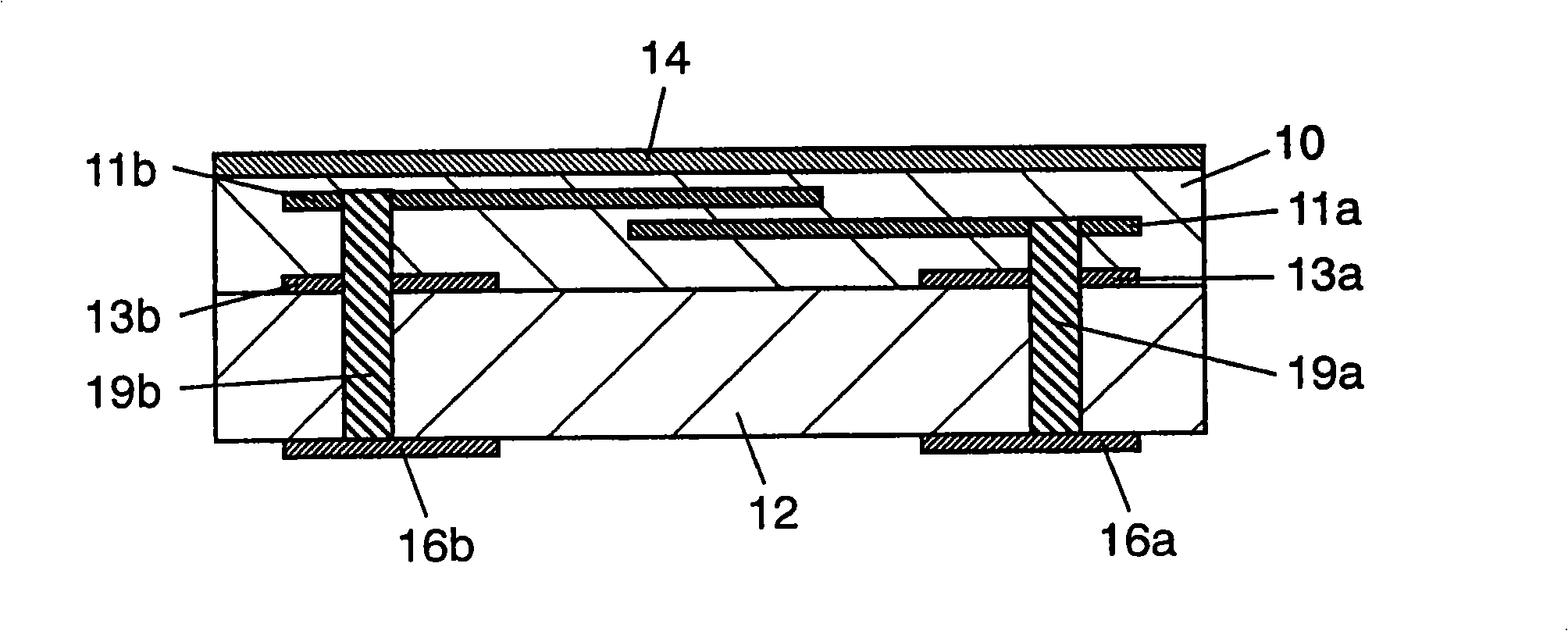
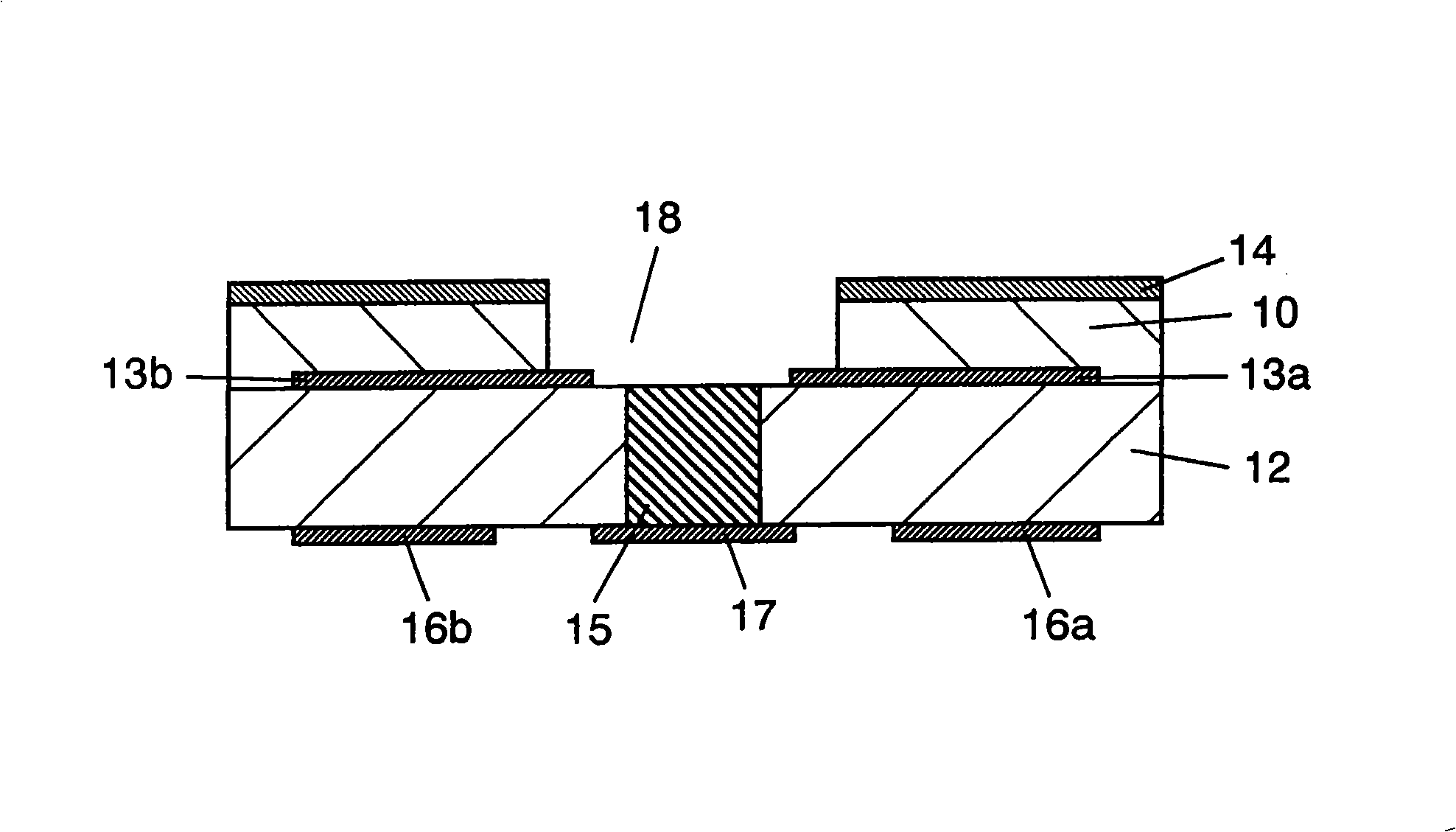
[0039] figure 1 It is an external perspective view of the electrostatic countermeasure component according to Embodiment 1 of the present invention. figure 2 It is the electrostatic countermeasure part of this embodiment figure 1 Sectional view of the 2-2 line. image 3 It is the electrostatic countermeasure part of this embodiment figure 1 Sectional view of the 3-3 line. Figure 4 It is a schematic exploded perspective view of the static electricity countermeasure part of this embodiment. Figure 5 It is a sectional view of the light emitting diode module of this embodiment. Figure 6 It is an equivalent circuit diagram of the light emitting diode module of this embodiment.

[0040] Such as figure 1 , figure 2 , image 3 and Figure 4 As shown, the anti-static component of this embodiment has a variable r...

no. 2 approach

[0073] Next, an electronic component and a light emitting diode module according to Embodiment 2 of the present invention will be described.

Embodiment approach 2

[0074] Embodiment 2 differs from Embodiment 1 in that, in Embodiment 1, the external electrodes 16a and 16b are formed on the surface of the ceramic substrate 12 opposite to the surface on which the terminal electrodes 13a and 13b are formed. In Mode 2, the external electrodes 16 a and 16 b are formed on the side surfaces of the varistor portion 10 and the ceramic substrate 12 .

[0075] Figure 12 It is an external perspective view of the static electricity countermeasure component of this embodiment. Figure 13 It is the electrostatic countermeasure part of this embodiment Figure 12 Sectional view of line 13-13. Figure 14 It is the electrostatic countermeasure part of this embodiment Figure 12 Sectional view of line 14-14. Figure 15 It is a schematic exploded perspective view of the static electricity countermeasure part of this embodiment. Figure 16 It is a sectional view of the light emitting diode module of this embodiment.

[0076] Such as Figure 12 , Figu...


PUM

PropertyMeasurementUnit
thicknessaaaaaaaaaa
thicknessaaaaaaaaaa
diameteraaaaaaaaaa

Abstract

An electrostatic discharge protection component comprising a ceramic sintered body having ceramic substrate 12 , varistor portion 10 formed thereon excluding some non-formed portion 18 , and glass ceramic layer 14 further formed thereon, a pair of terminal electrodes 13 a, 13 b disposed by exposing a part thereof at non-formed portion 18 on ceramic substrate 12 of the ceramic sintered body, a pair of external electrodes 16 a, 16 b, and heat conducting portion 15 vertically penetrating ceramic substrate 12 , a light-emitting diode or the like mounted on heat conducting portion 15 at non-formed portion 18 , it is possible to reduce the size and to efficiently dissipate the heat generated by the component mounted.

Description

technical field [0001] The present invention relates to a static electricity countermeasure component used in various electronic equipment as an electronic component protecting the electronic equipment from static electricity, and an electronic component module such as a light emitting diode module using the static electricity countermeasure component. Background technique [0002] In recent years, the miniaturization and low power consumption of electronic devices such as mobile phones have rapidly progressed, and with this, the withstand voltage of various electronic components constituting the circuits of the electronic devices has gradually decreased. [0003] Therefore, malfunctions of electronic equipment due to damage to various electronic components, especially semiconductor devices, caused by electrostatic pulses or the like generated when the human body comes into contact with the conducting portion of the electronic equipment increase. [0004] Furthermore, light-...

Claims


Application Information

Patent Timeline
Patent Type & Authority Applications(China)
IPC IPC(8): H01C7/10H01L33/00H01L33/62
CPCH01L2224/14H01L2224/48091H01L2224/48227
Inventor 井上龙也胜村英则叶山雅昭
Owner PANASONIC CORP
Why Eureka
Try Eureka