A mm wave section 4x4 cone common-shape dual-frequency micro-belt antenna and its design method

A millimeter-wave band and microstrip antenna technology, applied in antennas, antenna arrays, resonant antennas, etc., can solve problems such as the difficulty in the design of conical surface conformal dual-frequency microstrip antennas and the complex geometry of the cone surface, and achieve ideal simulation results. Clear, easy-to-model effects

Inactive Publication Date: 2008-09-17
HARBIN INST OF TECH
View PDF0 Cites 17 Cited by
  • Summary
  • Abstract
  • Description
  • Claims
  • Application Information

AI Technical Summary

Problems solved by technology

[0006] The purpose of the present invention is to solve the problem that it is extremely difficult to realize the design of the cone-shaped conformal dual-frequency microstrip antenna due to the relatively complicated geometry of the cone surface and the high frequency of the millimeter wave band, and to provide a A millimeter-wave band 4×4 conical conformal dual-band microstrip antenna and its design method

Method used


Image

  • A mm wave section 4x4 cone common-shape dual-frequency micro-belt antenna and its design method
  • A mm wave section 4x4 cone common-shape dual-frequency micro-belt antenna and its design method
  • A mm wave section 4x4 cone common-shape dual-frequency micro-belt antenna and its design method

Examples


specific Embodiment approach 1

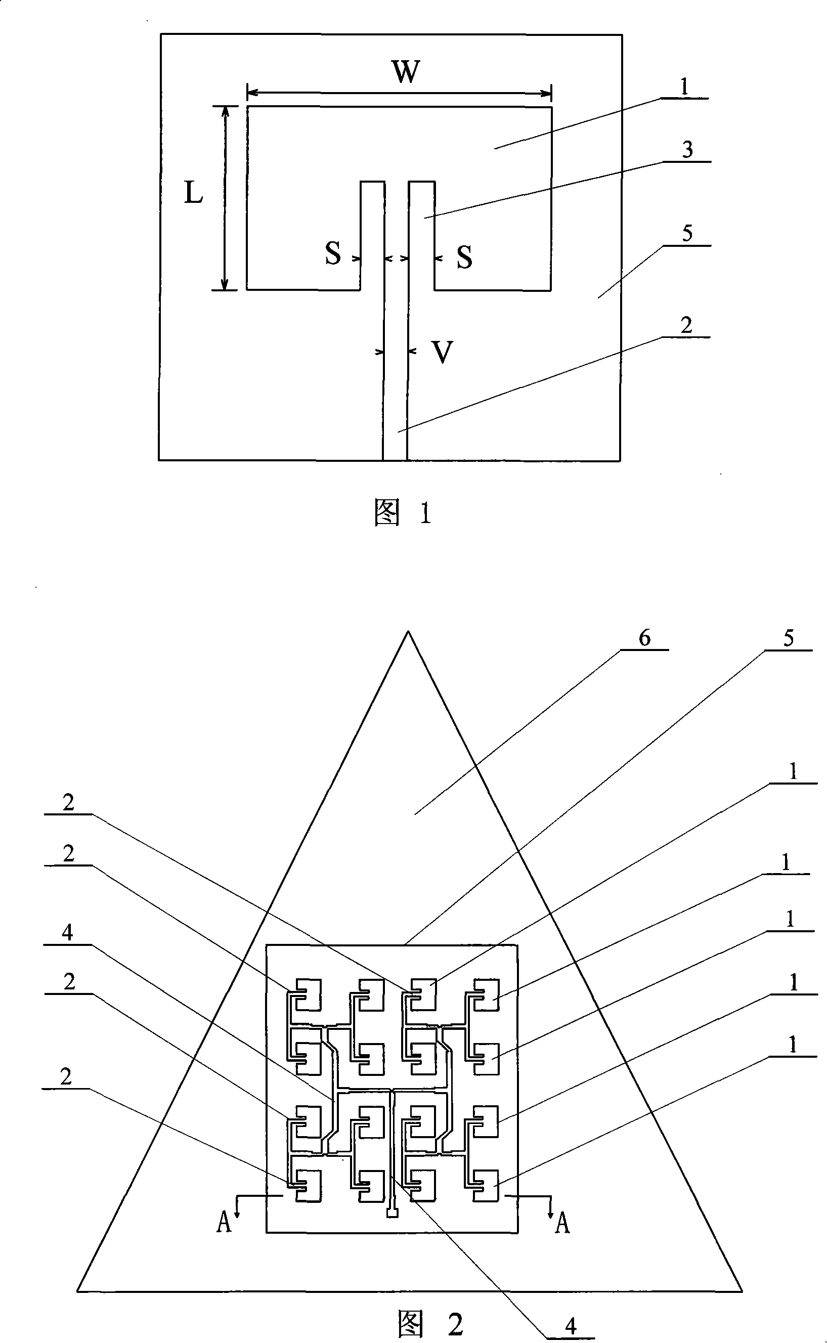
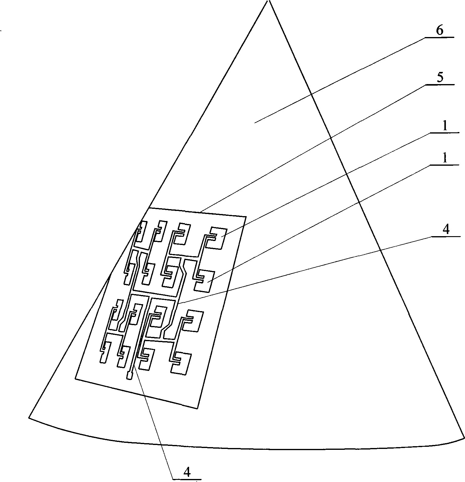
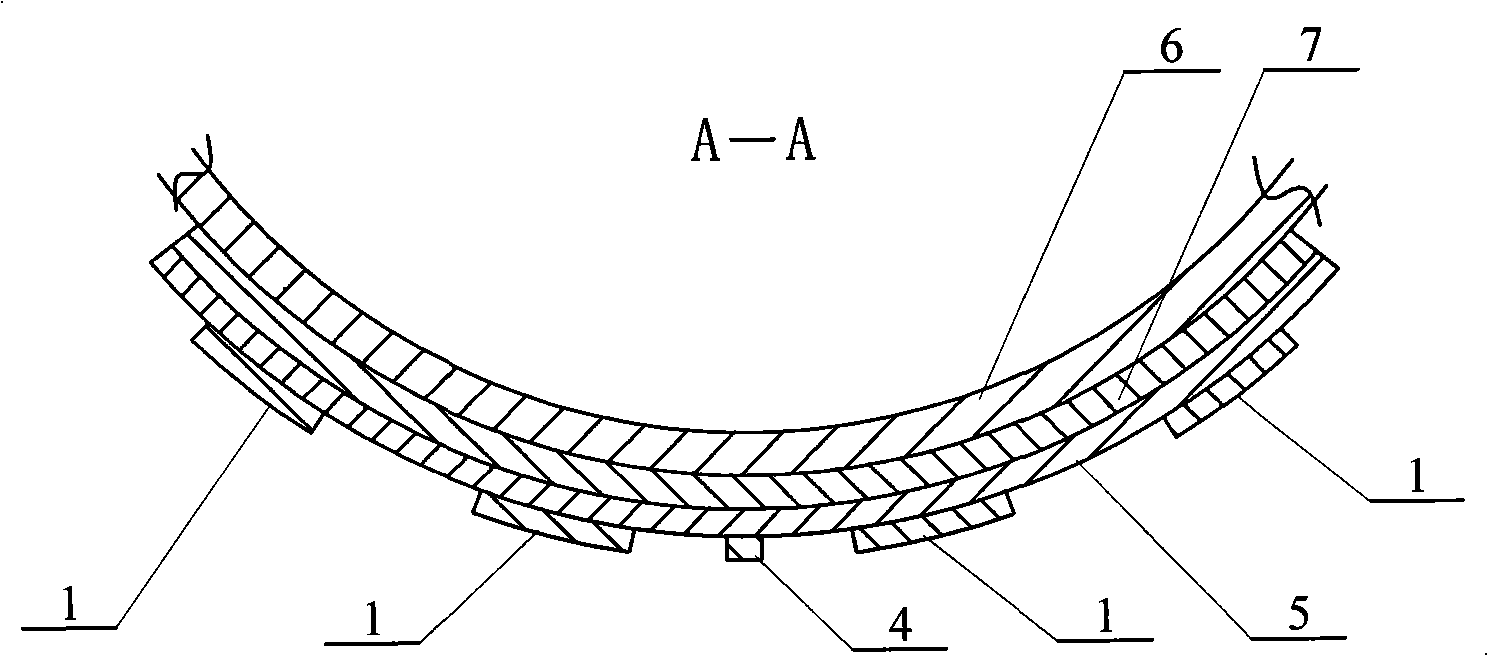
[0010] Specific implementation mode one: (referring to Fig. 1~ image 3 ) The millimeter-wave band 4×4 conical conformal dual-band microstrip antenna of this embodiment is composed of sixteen patch units 1, sixteen feeders 2, connection lines 4, dielectric layer 5, cone surface layer 6 and floor layer 7 , the sixteen patch units 1 are divided into four groups, and each group of four patch units 1 is arranged in a rectangular shape, and the four groups of patch units 1 are arranged in a rectangular shape on the surface of the dielectric layer 5 to form an array, and the back of the dielectric layer 5 It is fixedly connected to the surface of the floor layer 7, and the back of the floor layer 7 is fixedly connected to the surface of the cone surface layer 6. One end of each feeder 2 is connected with a patch unit 1 one-to-one, and each feeder 2 The other end of each is connected to the connection line 4. The material of the floor layer 7 is a perfect conductor (PEC).

specific Embodiment approach 2

[0011] Embodiment 2: (see FIG. 1 ) In this embodiment, a groove 3 is provided at the lower middle position of the chip unit 1 , and the top of the feeder 2 is connected to the bottom of the groove 3 at the lower side of the chip unit 1 . In this embodiment, the microstrip chip unit is fed by the groove-loaded intermediate feed mode, and its principle can be illustrated by the chip unit shown in FIG. 1 . Since the radiation of the patch part is interrupted by the feeding at the resonant side, the contact between the feeder and the patch leads to a reduction in radiation, which is particularly prominent in the millimeter wave band. Others are the same as in the first embodiment.

specific Embodiment approach 3

[0012] Embodiment 3: (see FIG. 1 ) The ratio of length (L) to width (W) of patch unit 1 in this embodiment is 1:1.1-1.4. Others are the same as in the first embodiment. Since the groove-loaded center feed method is adopted, the position of the feed line is fixed in the middle of the radiation side of the patch, and the resonant frequency of the antenna is only related to the length and width (L, W) of the patch, so it is only necessary to adjust L and W to make Antenna performance is optimal.


PUM


Abstract

The present invention provides a millimeter wave band 4*4 conical conformal dual-frequency microstrip antenna and its design method, relating to a microstrip antenna and its design method. The aim of the invention is resolving the problem of the difficult design of the present conical conformal dual-frequency microstrip antenna. The whole of the antenna four-group patch units shows rectangle provided on the surface of the dielectric layer to form an array, one end of each feeder is connected with one patch unit one by one. The method of the invention includes: deducting different thickness cone layer by the object function, extending the floor layer, the dielectric layer and the patch layer of the planar antenna to the cone layer, catching the intersection by the intersection function and conforming the planar array on the cone surface. The two resonant frequencies of the antenna are all in millimeter wave band, 30.6 and 35.5GHz respectively, the bandwidth of the conformal array on the two resonance points are 315MHz and 485MHz respectively. The invention has a simple structure, clearly arrangement, strict logic, relatively ideal simulation results, simply processing technology.

Description

technical field [0001] The invention relates to a microstrip antenna and a design method thereof. Background technique [0002] The application of high-tech in modern military equipment continues to increase, and the electronic components required by airborne, spaceborne and various weapon systems are moving towards the direction of short, small, light, thin, high reliability, high speed, multi-band and multi-polarization Rapid development. In terms of performance, there is an urgent need for high-performance array antennas that can work at multiple frequencies, have good electromagnetic compatibility, are not susceptible to electronic interference, have small radar cross section (RCS), and have stealth / anti-stealth characteristics. Especially as an important development direction of millimeter-wave guidance technology, the research on the antenna system that can conform to the carrier, that is, the conformal antenna, has been paid more and more attention in recent years. T...

Claims


Application Information

Patent Timeline
Patent Type & Authority Applications(China)
IPC IPC(8): H01Q21/00H01Q13/08H01Q9/16
Inventor 吴群傅佳辉孟繁义杨国辉刘敏冯子睿
Owner HARBIN INST OF TECH
Why Eureka
Try Eureka