Anti-fatigue controlled laser shot peening method and device therefor

A laser peening and anti-fatigue technology, which is applied in the direction of manufacturing tools, heat treatment process control, process efficiency improvement, etc., can solve the problems that have not yet been searched for controlled laser peening strengthening, and meet the strengthening requirements and improve work efficiency. Effect

Inactive Publication Date: 2008-10-01
JIANGSU UNIV
View PDF2 Cites 41 Cited by
  • Summary
  • Abstract
  • Description
  • Claims
  • Application Information

AI Technical Summary

Problems solved by technology

[0005] Research literature and related patents on controlled laser shot peening for anti-fatigue manufacturing have not yet been retrieved

Method used


Image

  • Anti-fatigue controlled laser shot peening method and device therefor
  • Anti-fatigue controlled laser shot peening method and device therefor
  • Anti-fatigue controlled laser shot peening method and device therefor

Examples


example

[0051] Example: Laser shot peening of 6061-T6 aviation aluminum alloy single-joint central hole fatigue test piece

[0052] Since laser shot peening is particularly suitable for dealing with fatigue parts with local stress concentration, such as machine parts with fatigue-prone notches, holes, and corners, and aluminum alloy is a commonly used aerospace material, 6061-T6 is selected in this example The aviation aluminum alloy single-joint center hole fatigue test piece is strengthened by laser shot peening, and its shape and size are as follows: Figure 4 As shown, the outer dimensions are machined first, and then the center hole is bored to a diameter of 2mm. The experiment adopts PLA30050 fatigue tensile testing machine. Before the laser shot peening of parts, when the maximum load is 7KN, the minimum load is 0.7KN, the stress ratio is 0.1, and the test frequency is 13HZ, the fatigue life is 88000. About times, it is now required to increase the fatigue life by more than 15...


PUM


Abstract

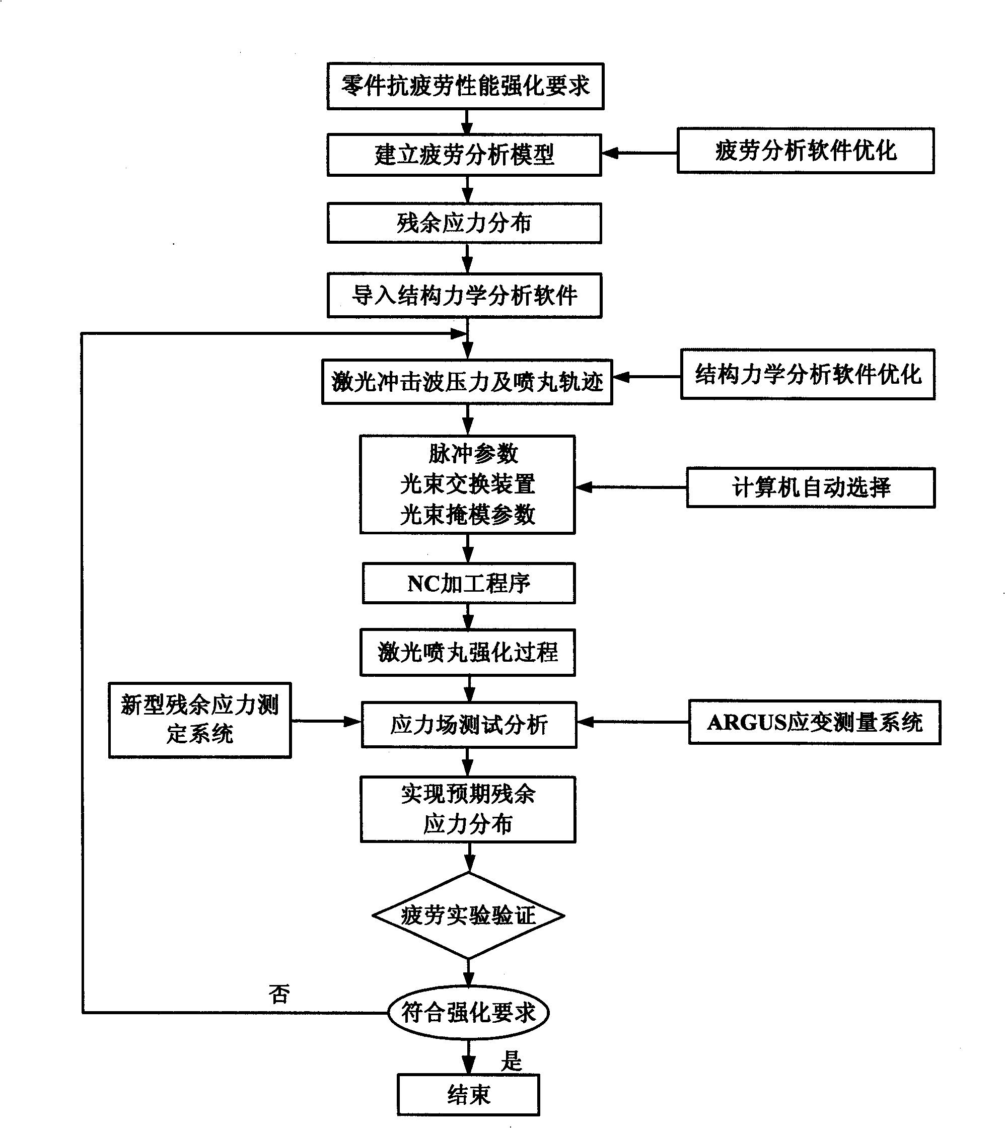
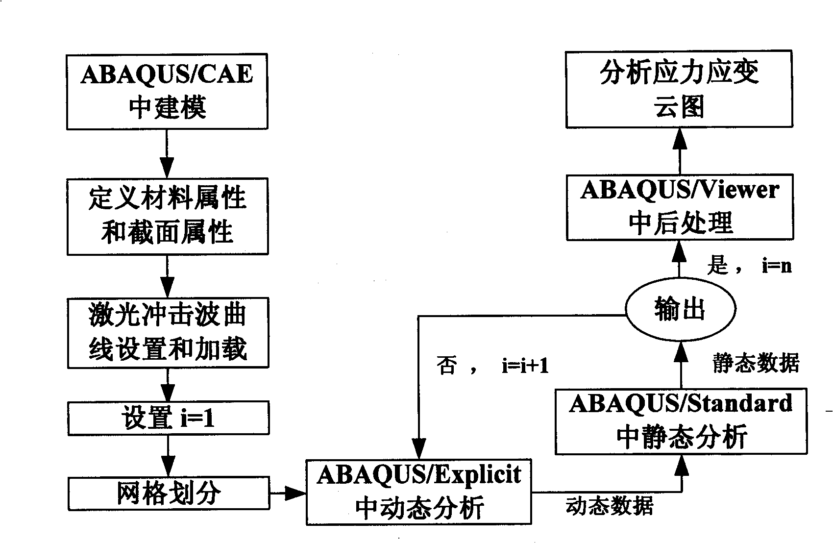
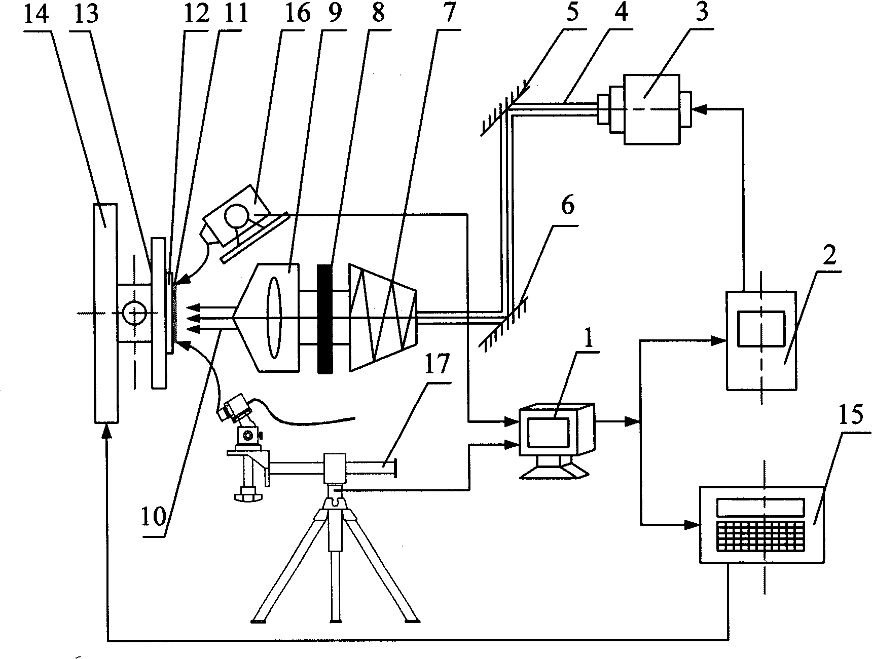
The invention relates to a method and a device for intensifying controlled laser shot peening, first of all, a fatigue analysis model is established in a fatigue analysis software, distribution of residual stress in the accessories is optimized in light of the expectant fatigue life value after the intensification to obtain the distribution of residual stress which meets the demand; the distribution of residual stress is imported into a structural mechanics CAE analysis software to obtain by optimization laser shock wave pressure acting on the surface of a sheet metal and the shot peening track; after than a computer control system automatically selects the pulse parameter and a light beam changing device while the laser shot peening; the laser emits a high energy short pulse laser beam to be converted into the high amplitude shock wave pressure acting on the surface of the accessories after being subjected to an optical changing device and an optical mask; a measurement feedback system is used to online check the distribution situation of the stress and strain on the surface layer of the accessories in the laser shot peening, the special computer software module is utilized to perform error analysis and parameter correction, ensuring to generate the expectant distribution of residual stress on the surface layer of the accessories to meet the intensification demand of the anti-fatigue performance.

Description

technical field [0001] The invention relates to the technical field of mechanical manufacturing and laser application, in particular to a method and a device for determining the corresponding residual stress distribution according to the fatigue resistance strengthening requirements of parts, and determining the laser shot peening process parameters according to the residual stress distribution. Background technique [0002] The rapid development of science and technology has put forward higher and higher requirements for the precision, performance and life of precision mechanical parts, and its use environment has become more and more harsh. Many mechanical structures must be subjected to high pressure, high temperature, high wear and high corrosion. use under external conditions. Various cracks and defects will inevitably appear during the processing of parts, and stress concentration areas will also emerge as the times require, resulting in damage or failure of parts. Th...

Claims


Application Information

Patent Timeline
IPC IPC(8): C21D1/09C21D11/00
CPCY02P10/20
Inventor 周建忠黄舒孙月庆陈毅彬盛杰蒋素琴
Owner JIANGSU UNIV
Why Eureka
Try Eureka