
Direct sodium borohydride-hydrazine mixed fuel cell

A sodium borohydride, fuel cell technology, applied in indirect fuel cells, fuel cells, fuel cell components and other directions, can solve the problems of no application, poor reaction activity, poor performance, etc., to improve stability and increase production. Hydrogen, the effect of improving work efficiency

Inactive Publication Date: 2008-10-01
ZHEJIANG UNIV
View PDF1 Cites 10 Cited by
  • Summary
  • Abstract
  • Description
  • Claims
  • Application Information

AI Technical Summary

Problems solved by technology

However, because the reactivity of hydrazine is worse than that of sodium borohydride, the performance of direct hydrazine fuel cells using only hydrazine as fuel is not as good as that of direct sodium borohydride fuel cells, so direct hydrazine fuel cells have not been applied so far.

Method used


Image

  • Direct sodium borohydride-hydrazine mixed fuel cell
  • Direct sodium borohydride-hydrazine mixed fuel cell
  • Direct sodium borohydride-hydrazine mixed fuel cell

Examples


Embodiment 1

[0051] Embodiment 1: the modulation of sodium borohydride-hydrazine mixed hydrogen generation solution

[0052] At room temperature, dissolve 100g of sodium borohydride in 500ml of water and hydrazine (N 2 h 4 ·H 2 0), the granular sodium hydroxide of 50g is dissolved in 400ml distilled water, after stirring at room temperature, obtain sodium borohydride-hydrazine alkaline mixed fuel.

Embodiment 2

[0053] Embodiment 2: the preparation of direct fuel cell (1)

[0054] A direct fuel cell contains an anode, an anion exchange membrane, and a cathode. The cathode is a purchased platinum carbon electrode, and the coating amount of platinum is 1mg Pt / cm 2 , the anode is the purchased palladium carbon electrode, and the coating amount of palladium is 1mgPd / cm 2 . The catalyst is coated on carbon fiber paper, and the side of the electrode coated with the catalyst is facing the anion exchange membrane, at 100kg / cm 2 , Hot pressing at 150 degrees to make a membrane electrode, and assemble a direct fuel cell with a plate engraved with a flow path.

Embodiment 3

[0055] Embodiment 3: the preparation of direct fuel cell (2)

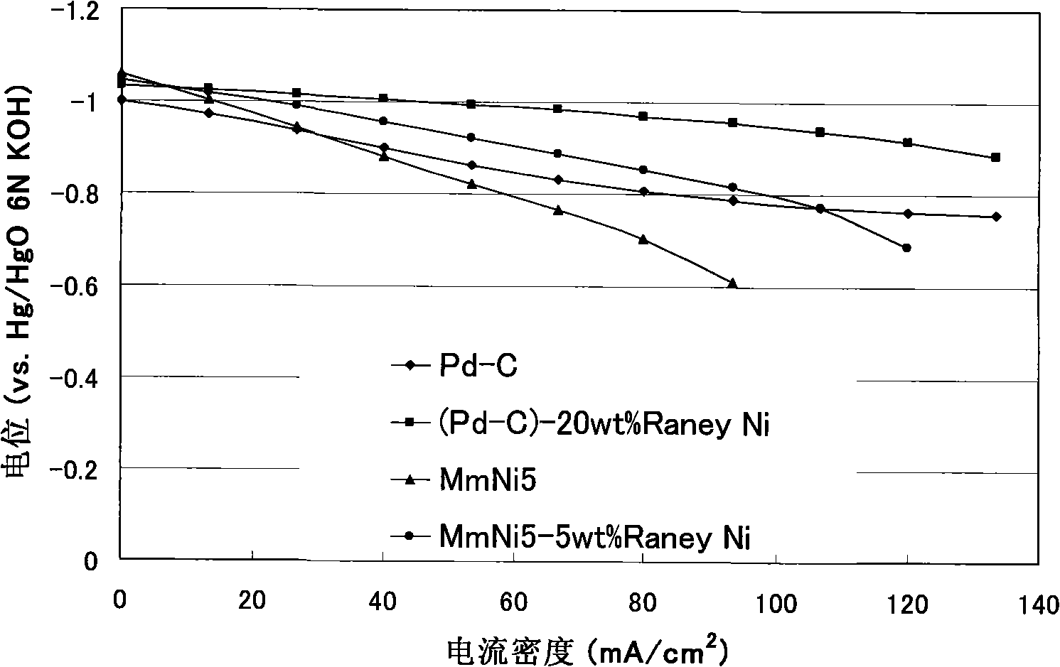
[0056] A direct fuel cell contains an anode, an anion exchange membrane, and a cathode. The cathode is a platinum carbon electrode, and the coating amount of platinum is 1mg Pt / cm 2 , the anode catalyst is a metal hydride (MmNi 5 ). MmNi 5 The preparation method of the catalyst is: weigh 20g of hydrogen storage material, put it into a ball mill tank, which contains 7 stainless steel balls with a diameter of 1 cm, then add the 0.2M aqueous solution of the precursor of the above catalyst, tighten the cover, and produce it through a high-speed planetary mill. With an acceleration of 1G, ball milling at room temperature for 90 minutes, rinsing with distilled water for 5 times, and vacuum drying below 80°C for 3 hours, MmNi was obtained. 5 Catalyst 18g. Add 54ml of distilled water, 54ml of ethanol, 126ml of perfluoropolysulfonic acid resin of 5wt%, 9ml of glycerin, and mix uniformly with ultrasonic waves to form a ...


PUM


Abstract

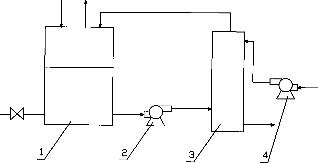
The invention discloses a blended fuel cell, which is for the purpose of providing a direct-like sodium borohydride-hydrazine blended fuel cell. The blended fuel cell includes a fuel cell connected with an air blower, a fuel tank, a miniature transfer pump, wherein, the bottom outlet of the fuel tank connects with the miniature transfer pump and the fuel cell in sequence through pipelines, the outlet of the fuel cell is connected with the upside of the fuel tank, on the upside of which an air vent and a fuel filling opening are arranged, and on the lower part of which a residue outlet is arranged; a fuel solution is circulated through the miniature transfer pump; the fuel in the fuel tank is a sodium borohydride-hydrazine-water solution, wherein, the hydrazine is a chemical hydride whose hydrogen content is higher than that of the sodium borohydride, after the hydrazine is added, not only is the stability of the sodium borohydride improved, but also the energy density of the fuel can be enhanced, so that the producing of the hydrogen is easy, the energy density is higher, and the working efficiency of the fuel cell is improved.

Description

technical field [0001] The invention relates to a hybrid fuel cell, more specifically, the invention relates to a direct sodium borohydride-hydrazine hybrid fuel cell. Background technique [0002] Sodium borohydride is a complex hydride with relatively high hydrogen content (hydrogen content 10.8 wt%), and is a white solid. Hydrazine is a higher hydrogen covalent hydride (12.5 wt% hydrogen). USP5,599,640(1997) and USP5,804,329(1998) are related to direct sodium borohydride fuel cell, and Japanese patent application 2002-339694 is related to using hydrogen peroxide as an oxidant. [0003] Sodium borohydride can be directly electrochemically oxidized at normal temperature and pressure to generate electricity. Compared with other hydrogen storage methods, it has the characteristics of high hydrogen storage capacity of fuel, high electromotive force, and high theoretical energy conversion efficiency. In recent years, direct sodium borohydride fuel cell, as a new type of fuel ...

Claims


Application Information

Patent Timeline
IPC IPC(8): H01M8/06H01M8/20C01B31/04H01M8/10H01M8/02H01M4/90H01M4/86H01M8/00H01M8/0202H01M8/04186H01M8/1009
CPCY02E60/521Y02E60/528Y02E60/50
Inventor 李洲鹏刘宾虹朱京科
Owner ZHEJIANG UNIV
Learn More